
Tunable Optical Filter

a tunable optical filter and filter technology, applied in the field of tunable optical filters, can solve the problems of large power consumption, slow tuning speed, and limited prior art tunable optical filters

Inactive Publication Date: 2007-02-22
JDS UNIPHASE INC
View PDF2 Cites 24 Cited by
  • Summary
  • Abstract
  • Description
  • Claims
  • Application Information

AI Technical Summary

Benefits of technology

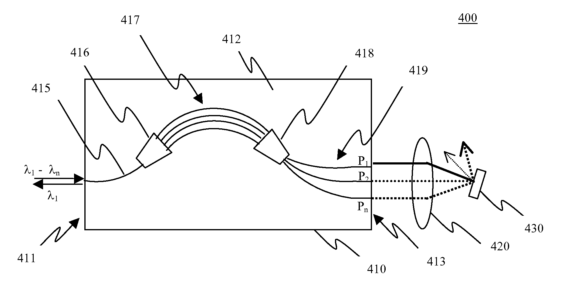
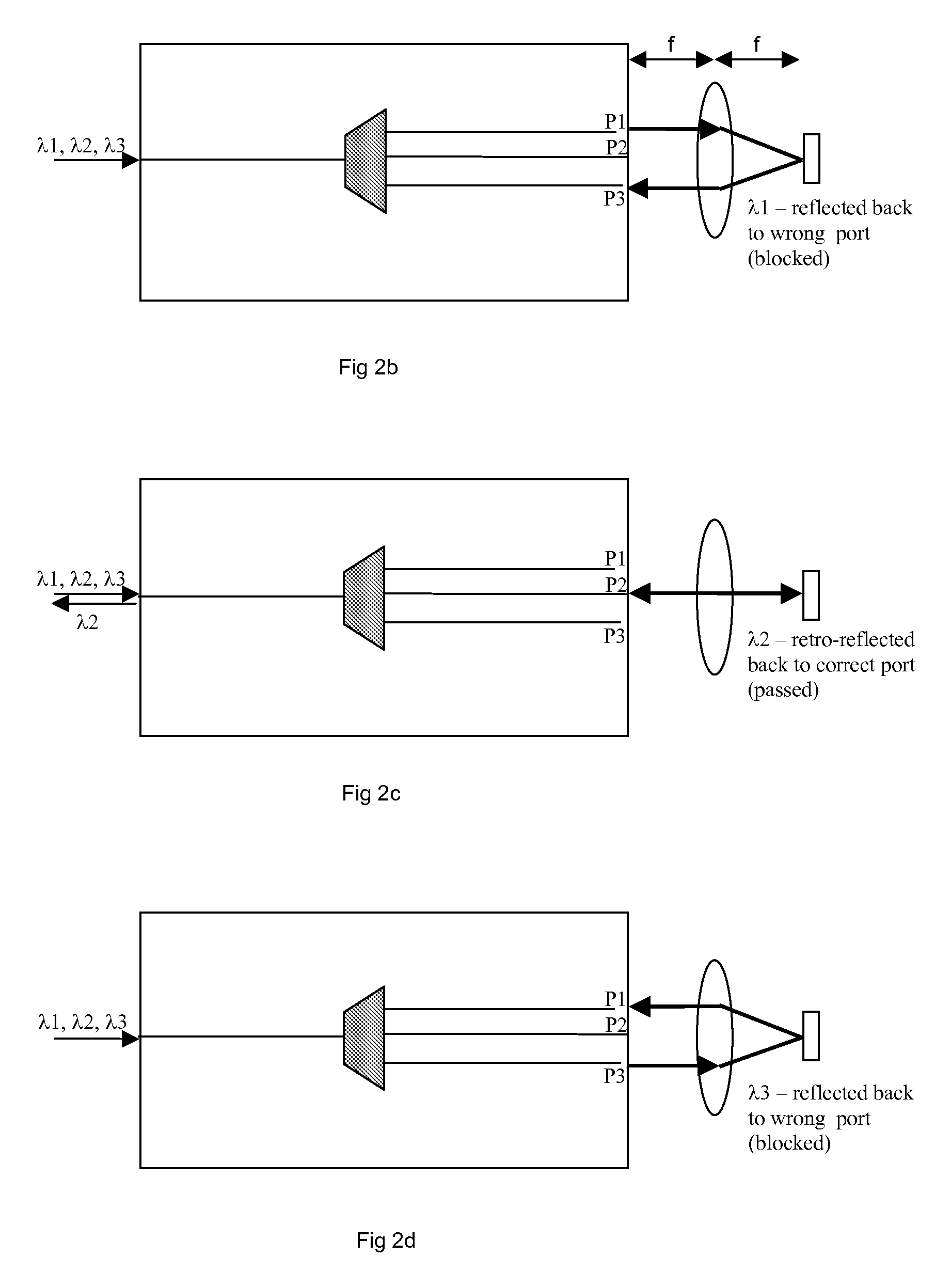
[0010] In accordance with one aspect of the instant invention there is provided a tunable optical filter comprising: a demultiplexing device for separating a multiplexed optical signal into a plurality of demultiplexed optical signals, each demultiplexed optical signal including a different wavelength channel; an imaging element for converging the plurality of demultiplexed optical signals to a common point; and a reflector disposed at the common point, the reflector tiltable about a first axis to a first position wherein one of the demultiplexed optical signals in the plurality is reflected with an angle that allows it to repass through the demultiplexing device and be output from an output port of the tunable optical filter and the remaining optical signals in the plurality are reflected with angles preventing them from repassing through the demultiplexing device and being output the output port of the tunable optical filter.

Problems solved by technology

Currently, prior art tunable optical filters are generally limited by slow tuning speed, large power consumption, narrow tuning range, large insertion loss, poor adjacent channel isolation, bulky size and / or complex and high cost manufacturing processes.

Method used


Image

  • Tunable Optical Filter
  • Tunable Optical Filter
  • Tunable Optical Filter

Examples


Embodiment Construction

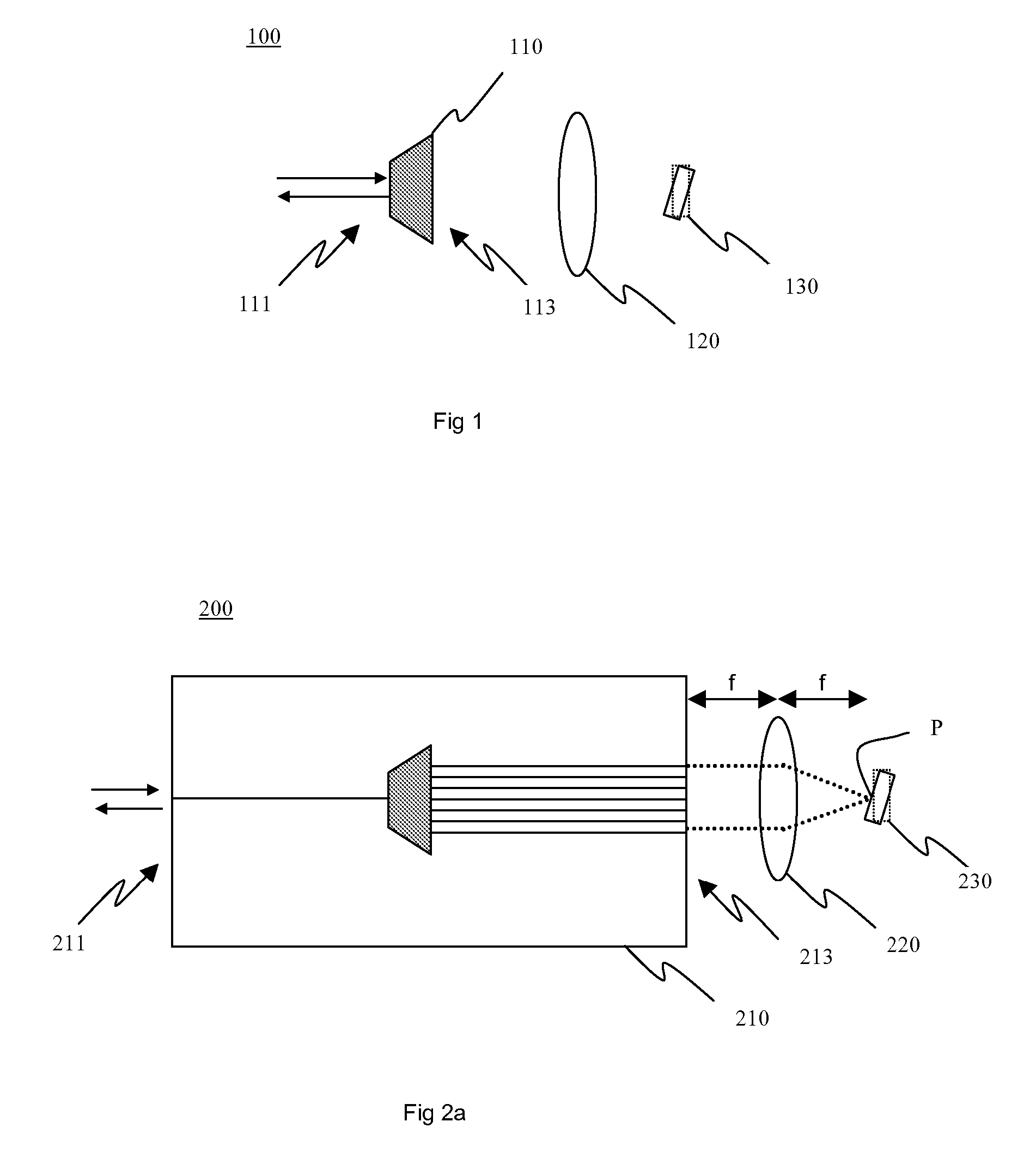
[0034] Referring to FIG. 1, a schematic diagram of a tunable optical filter according to one embodiment of the instant invention is shown. The tunable optical filter 100 includes a demultiplexing device 110, an element having optical power 120, and a tiltable reflector 130.

[0035] The demultiplexing / multiplexing device 110 provides wavelength demultiplexing in the forward direction and wavelength multiplexing in the reverse direction. More specifically, the demultiplexing device is used to separate a multiplexed optical signal having n different wavelength channels into n different sub-signals, each sub-signal corresponding to a different wavelength channel. The multiplexed optical signal is launched into the demultiplexing device 110 at an first input / output end 111 thereof, and the demultiplexed optical sub-signals are output from a second input / output end 113 thereof. The demultiplexed outputs are typically spatially or angularly separated.

[0036] The element having optical power...


PUM


Abstract

A tunable optical filter includes a demultiplexing device, such as an arrayed waveguide grating (AWG) or echelle grating, for separating a multiplexed optical signal into a plurality of demultiplexed optical signals. An imaging lens converges the plurality of demultiplexed optical signals to a common point on a tiltable reflector, which for example is a microelectromechanical system (MEMS) mirror. The tiltable reflector is rotated about a first axis to select which one of the demultiplexed optical signals in the plurality the tunable optical filter is tuned to. More specifically, the tiltable reflector is rotated about the first axis to select which one of the demultiplexed optical signals will be reflected with an angle that allows it to repass through the demultiplexing device and be output from an output port of the tunable optical filter.

Description

CROSS-REFERENCE TO RELATED APPLICATIONS [0001] This application claims priority from U.S. provisional application No. 60 / 708,382 filed Aug. 16, 2005, which is hereby incorporated by reference.MICROFICHE APPENDIX [0002] Not Applicable. TECHNICAL FIELD [0003] The present application relates generally to tunable optical filters, and in particular, to tunable optical filters for optical communications systems and optical devices including the same. BACKGROUND OF THE INVENTION [0004] Optical communication systems increasingly use wavelength-division multiplexing (WDM) to increase bandwidth. In WDM and / or dense WDM (DWDM) systems multiple optical data signals, each in a different wavelength range or channel, are combined as a single multiplexed optical signal and transmitted through a single optical waveguide. [0005] Optical filters are useful in WDM systems for extracting a specific wavelength channel from the multiplexed optical signal. Tunable optical filters are particularly desirable...

Claims


Application Information

Patent Timeline
Patent Type & Authority Applications(United States)
IPC IPC(8): G02B6/293G02B6/34
CPCG02B6/12019G02B6/2938G02B6/29395G02B6/3512G02B6/356
Inventor KEYWORTH, BARRIE
Owner JDS UNIPHASE INC
Learn More