
Stereoscopic 3D-video image digital decoding system and method

Inactive Publication Date: 2007-02-22
TDVISION CORP SA DE CV
View PDF34 Cites 44 Cited by
  • Summary
  • Abstract
  • Description
  • Claims
  • Application Information

AI Technical Summary

Benefits of technology

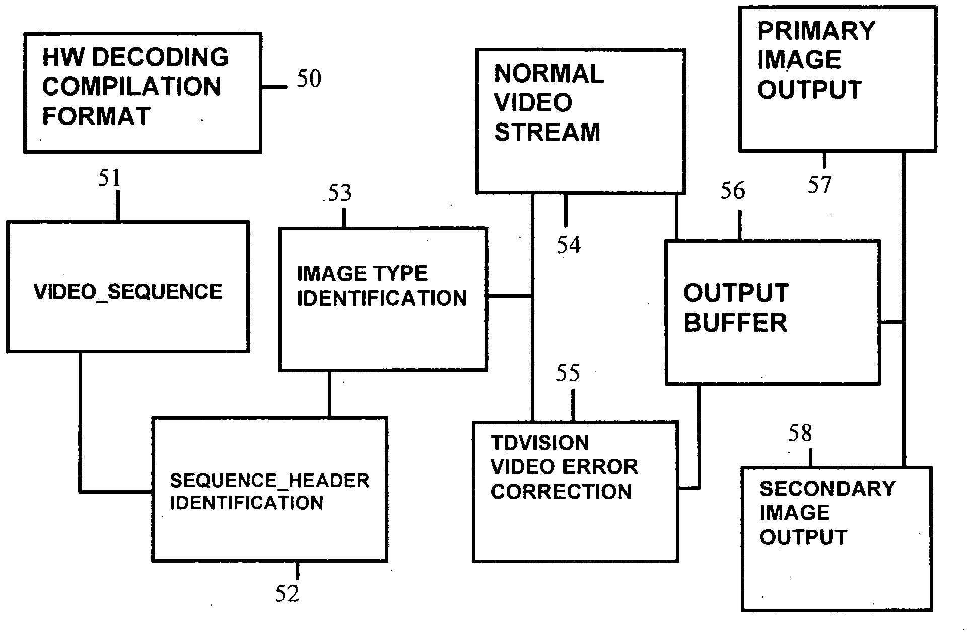
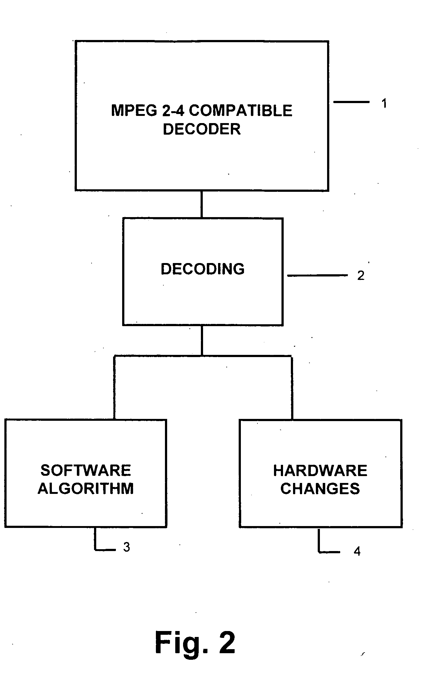
[0025] It is an object of the present invention to provide a stereoscopic 3D-video image digital decoding system and method, comprised of changes in software and changes in hardware.
[0026] It is an additional object of the present invention to provide a decoding method where the normal video_sequence process is applied to the coded image data, i.e.variable_length decoding (VLD), inverse_scan; inverse_quantization, inverse_discrete_cosine_transform (IDCT), and motion_compensation.
[0026] It is an additional object of the present invention to provide a decoding method where the normal video_sequence process is applied to the coded image data, i.e.variable_length decoding (VLD), inverse_scan; inverse_quantization, inverse_discrete_cosine_transform (IDCT), and motion_compensation.
[0029] It is also another object of the present invention to provide a decoding process in which two interdependent (difference) video signals can be sent within the same video_sequence, in which information decoding is applied and is stored as a B type frame.
[0030] It is still another object of the present invention to provide a decoding process in which error correction is applied to the last obtained image when the movement and color correction vectors are applied.
[0034] It is also another object of the present invention to provide a 3D-image information decoding system, which executes the decompression process and displays the corresponding output buffer.
[0034] It is also another object of the present invention to provide a 3D-image information decoding system, which executes the decompression process and displays the corresponding output buffer.

Problems solved by technology

The transport stream is used in systems with a greater error possibility, such as satellite systems, which are susceptible to interference.

Method used


Image

  • Stereoscopic 3D-video image digital decoding system and method
  • Stereoscopic 3D-video image digital decoding system and method
  • Stereoscopic 3D-video image digital decoding system and method

Examples


Embodiment Construction

[0040] The combination of hardware and software algorithms makes possible the stereoscopic 3D-image information compression, which are received as two independent video signals but with the same time_code, corresponding to the left and right signals coming from a 3Dvision® camera, by sending two simultaneous programs with stereoscopic pair identifiers, thus promoting the coding-decoding process. Also, two interdependent video signals can be handled by obtaining their difference, which is stored as a “B” type frame with the image type identifier. As the coding process was left open in order to promote the technological development, it is only necessary to follow this decoding process, namely: apply variable-length decoding to the coded data where a substantial reduction is obtained, but a look-up table should be used to carry out decoding; apply an inverse scan process; apply an inverse quantization process in which each data is multiplied by a scalar; apply the inverse cosine transf...


PUM


Abstract

Described herein is a MPEG-2 compatible stereoscopic 3D-video image digital decoding method and system. In order to obtain 3D-images from a digital video stream, modifications are made to the current MPEG2 decoders, by means of software and hardware changes in different parts of the decoding process. Namely, the video_sequence structures of the video data stream are modified via software to include the necessary flags at the bit level of the image type in the TDVision® technology. Modifications are also made in the decoding processes as well as in decoding the information via software and hardware, wherein a double output buffer is activated, a parallel and difference decoding selector is activated, the decompression process is executed, the corresponding output buffer is displayed; and the decoder is programmed via software to simultaneously receive and decode two independent program streams, each with an TDVision® stereoscopic identifier.

Description

CROSS-REFERENCE TO RELATED APPLICATION [0001] This application is a continuation of PCT Application No: PCT / MX2004 / 000012 filed on Feb. 27, 2004 in the Spanish language.FIELD OF THE INVENTION [0002] The present invention is related to stereoscopic video image display in the 3DVisor® device and, particularly, to a video image decoding method by means of a digital data compression system, which allows the storage of three-dimensional information by using standardized compression techniques. BACKGROUND OF THE INVENTION [0003] Presently, data compression techniques are used in order to decrease the bits consumption in the representation of an image or a series of images. The standardization works were carried out by a group of experts of the International Standardization Organization. Presently, the methods are usually known as JPEG (Joint Photographic Expert Group), and MPEG (Moving Pictures Expert Group). [0004] A common characteristic of these techniques is that the image blocks are ...

Claims


Application Information

Patent Timeline
IPC IPC(8): H04N11/04H04N11/02G06T9/00G06T15/00H04N7/26H04N7/50H04N13/00H04N19/593
CPCH04N19/597H04N19/70H04N19/30H04N19/42H04N19/593H04N19/44H04N19/61H04N13/00
Inventor GUTIERREZ NOVELO, MANUEL RAFAEL
Owner TDVISION CORP SA DE CV
Learn More