Eureka AIR delivers breakthrough ideas for toughest innovation challenges, trusted by R&D personnel around the world.

Aerospace light-emitting diode (LED)-based lights life and operation monitor compensator

a technology of light-emitting diodes and monitors, which is applied in the direction of identification means, instruments, process and machine control, etc., can solve problems such as unpredicted malfunctions, potential malfunctions, and degradation or failure of leds over time, and achieve the effect of not regulating the light control system and preventing malfunctions

Active Publication Date: 2007-02-22
HONEYWELL INT INC
View PDF25 Cites 98 Cited by
  • Summary
  • Abstract
  • Description
  • Claims
  • Application Information

AI Technical Summary

Benefits of technology

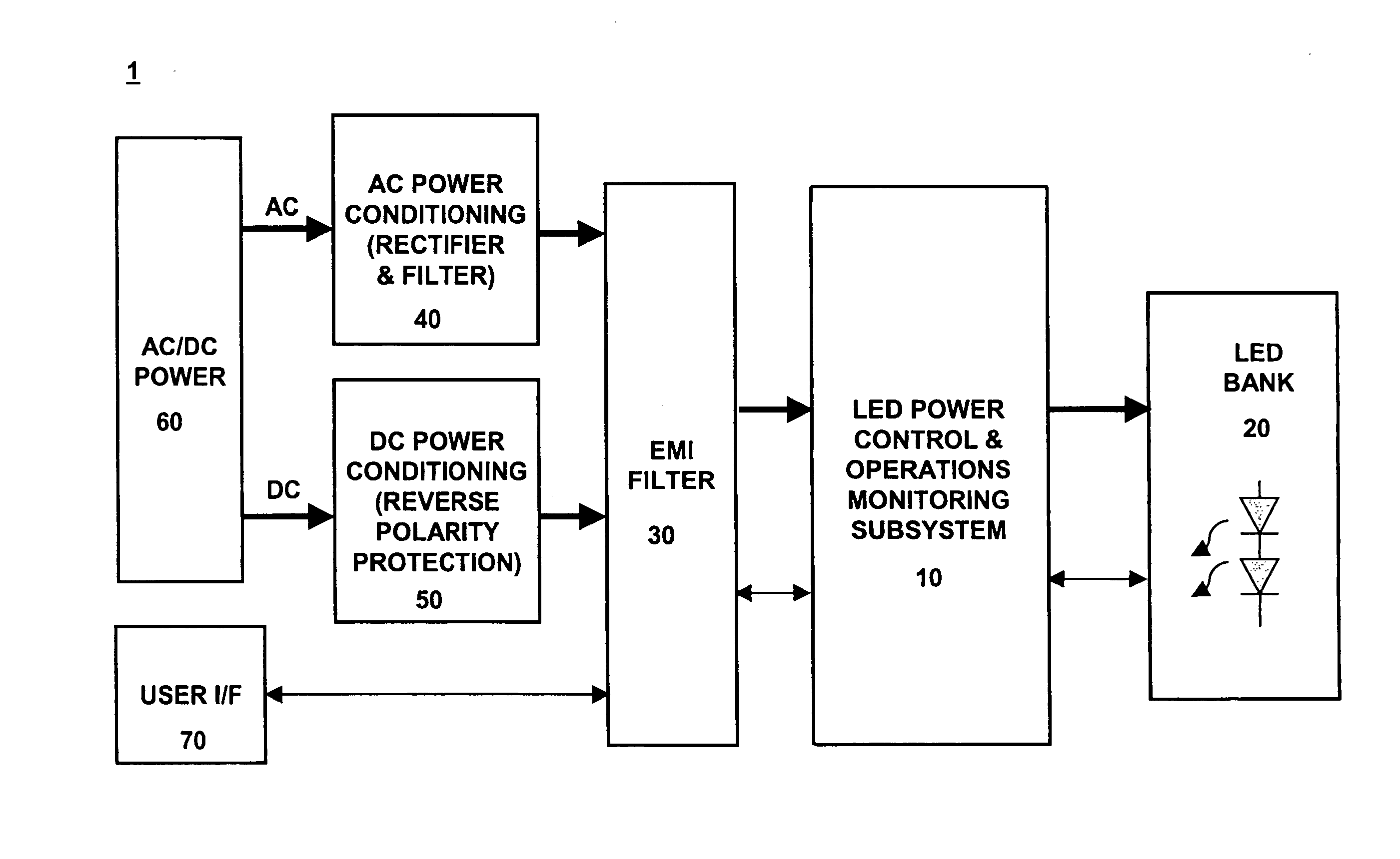
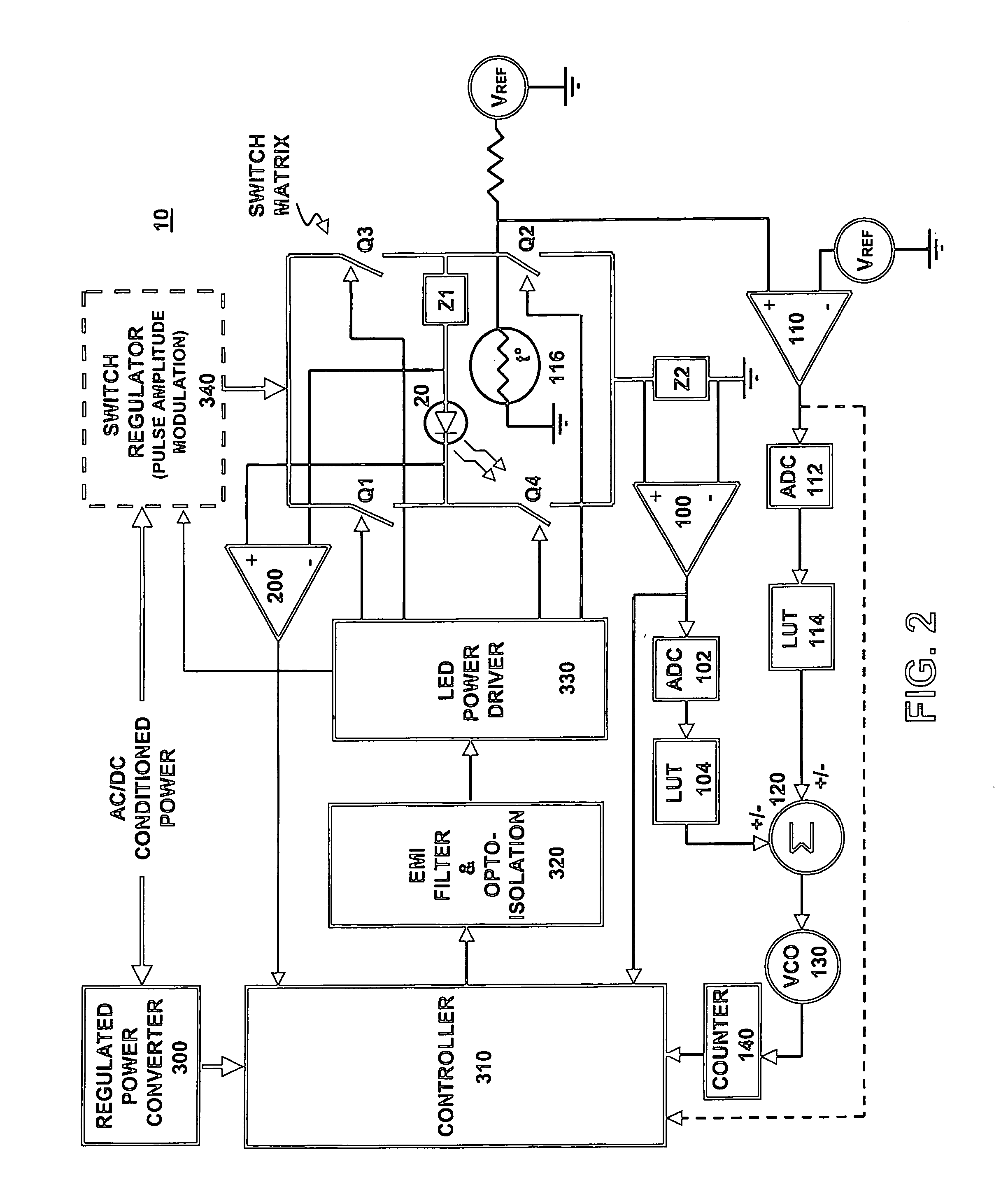
The present invention is about monitoring the life and performance of LED-based lighting devices. One way to do this is by measuring the amount of time the LED is in operation and compensating for this by using measurements of LED current or temperature. Another way to monitor the LED's performance is by measuring its electrical characteristics, such as voltage or current, and testing for failure conditions based on these measurements. The technical effects of this invention include improved monitoring and control of LED lighting devices, leading to better performance and reliability.

Problems solved by technology

In such flight-critical applications, the degradation or failure of LEDs that occurs over time is a concern.
Without adequate monitoring of the operational health of such LEDs, the potential exists for unpredicted malfunctions.
Such malfunctions may include overall failure (e.g., a short circuit or open circuit condition), or illumination at a level which is substantially below that dictated by flight regulations.
However, existing LED-based lights are mainly dependent on passive, open-loop control systems.
Such control systems do not regulate the lights based on key factors that affect LED operation, e.g., current and diode junction temperature.
Also, these previous lighting systems lack the “intelligence” to monitor the key LED parameters in order to estimate remaining operational life and predict future performance of the installed LEDs.
In addition, such systems do not provide a way to test for failure conditions while the LEDs are turned off.

Method used


Image

  • Aerospace light-emitting diode (LED)-based lights life and operation monitor compensator
  • Aerospace light-emitting diode (LED)-based lights life and operation monitor compensator
  • Aerospace light-emitting diode (LED)-based lights life and operation monitor compensator

Examples


Embodiment Construction

[0018] An exemplary embodiment of the present invention is directed to a system that monitors the operational life and / or performance of one or more LEDs installed in an LED-based lighting device. According to an exemplary embodiment, monitoring LED performance may include both measuring operational characteristics of an LED when it is activated (turned on), or testing for failure conditions when the LED is deactivated (turned off).

[0019] Such an LED-based lighting device may be designed for aerospace applications. For instance, the present invention may be used to monitor LEDs in flight-critical lighting systems, such as an aircraft's exterior warning lights (anti-collision lights, forward position lights, etc.) or interior instrumentation lights (e.g., indicators on the pilot's control console). In such applications, the LED-based lighting device may be powered by a “wild frequency” AC power supply in the aircraft. Alternatively, a DC power source (e.g., battery) may be installed...


PUM


Abstract

A system (10) and method for monitoring the operational life and / or performance of one or more light-emitting diodes (LEDs) (20) based on sensed parameters are disclosed. The remaining life of each LED may be predicted by counting the clock cycles during which the LED-based light is activated. LED current and / or temperature measurements may be used to control the clock signal and, thus, to compensate the predicted life value. Furthermore, operational characteristics of the LED-based light may be monitored based on LED current and / or voltage measurements. Such characteristics may include performance (e.g., intensity) and failure conditions (e.g., open or short circuits).

Description

FIELD OF THE INVENTION [0001] The present invention is directed to monitoring the operational condition of light-emitting diode (LED)-based lighting devices and, more particularly, to sensing LED parameters affecting the operation of such devices. BACKGROUND OF THE INVENTION [0002] Light-emitting diodes (LED) are becoming increasingly used over other types of lights because of advantages in heat and power dissipation, as well as operational life. For example, LEDs are being used in various aerospace applications, including interior instrumentation lights of aircraft for providing flight control information to pilots, and exterior aircraft warning lights (e.g., anti-collision lights) for alerting others as to the aircraft's position and location. [0003] In such flight-critical applications, the degradation or failure of LEDs that occurs over time is a concern. Without adequate monitoring of the operational health of such LEDs, the potential exists for unpredicted malfunctions. Such m...

Claims


Application Information

Patent Timeline
Patent Type & Authority Applications(United States)
IPC IPC(8): G08B21/00
CPCG01R31/2635H05B33/0818H05B33/0893B64F5/60H05B37/03H05B33/0851B64D47/02H05B45/18H05B45/3725H05B45/58H05B47/20
Inventor MUBASLAT, SAED M.KIRKPATRICK, TERENCE D.MACHI, NICOLO F.
Owner HONEYWELL INT INC
Why Eureka
Eureka Blog
Learn More