Method of obtaining a characteristic, and hearing instrument

a characteristic and hearing technology, applied in the field of hearing instruments, can solve the problems of large calculation power consumption, large occlusion of feedback control, and limited accuracy of such a model system

Inactive Publication Date: 2007-02-15
PHONAK
View PDF6 Cites 86 Cited by
  • Summary
  • Abstract
  • Description
  • Claims
  • Application Information

AI Technical Summary

Benefits of technology

[0005] It is an object of the invention to provide a method of operating a hearing instrument, a hearing instrument, and a method of manufacturing a hearing instrument which address the problem of uncertain coupling of the hearing instrument to the individual ear of a user and which overcome drawbacks of prior art approaches and especially do not require too much calculation power to be used.
[0018] According to the invention, the hearing instrument's signal processing unit may calculate a characteristic of the ear canal which is used for optimized signal processing, for example for adapting a gain to the individual properties of the ear canal (vent leakage, impedance, etc.). Therefore, on the one hand, a separate device for measuring ear canal characteristic is not necessary, and the user of the hearing instrument does not have to go to the hearing aid professional in order to adapt the hearing instrument to the ear canal characteristic. On the other hand, the approach in accordance with the invention eliminates the need for a control loop—as has been presented in the state of the art—which would use up a lot of calculating power. Also, in contrast to the state of the art, a stored characteristic may not only be used for controlling and correcting the actually perceived signal by way of a gain adjustment but may be used for other purposes as well, including diagnostic purposes, as will be explained in the following.
[0028] The values may for example be stored in the signal processing unit as the RECD values. Storing of RECD values for signal processing has been known in state-of-the-art hearing instruments. In state-of-the-art hearing instruments, however, the RECD values are determined indirectly during a fitting process. One advantage of the first aspect of the invention, therefore, may be to simplify the fitting process.

Problems solved by technology

The accuracy of such a model system is limited.
As a consequence, when hearing instruments are set up in accordance with the needs of a user, the problem of the uncertain RECD given the individual ear canal parameters arises.
Such a feedback control, however, uses up a lot of calculation power.

Method used


Image

  • Method of obtaining a characteristic, and hearing instrument
  • Method of obtaining a characteristic, and hearing instrument
  • Method of obtaining a characteristic, and hearing instrument

Examples


Embodiment Construction

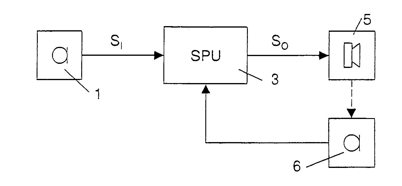
[0068] The hearing instrument of FIG. 1 comprises at least one outer acoustic-to-electric converter (microphone) 1 (often, two or even three acoustic-to-electric converters are available in each hearing instrument), a signal processing unit (SPU) 3 operable to apply a time- and / or frequency-dependent gain to the input signal or input signals S1 resulting in an output signal SO and at least one electric-to-acoustic converter (receiver) 5. The hearing instrument further comprises an inner acoustic-to-electric converter 6.

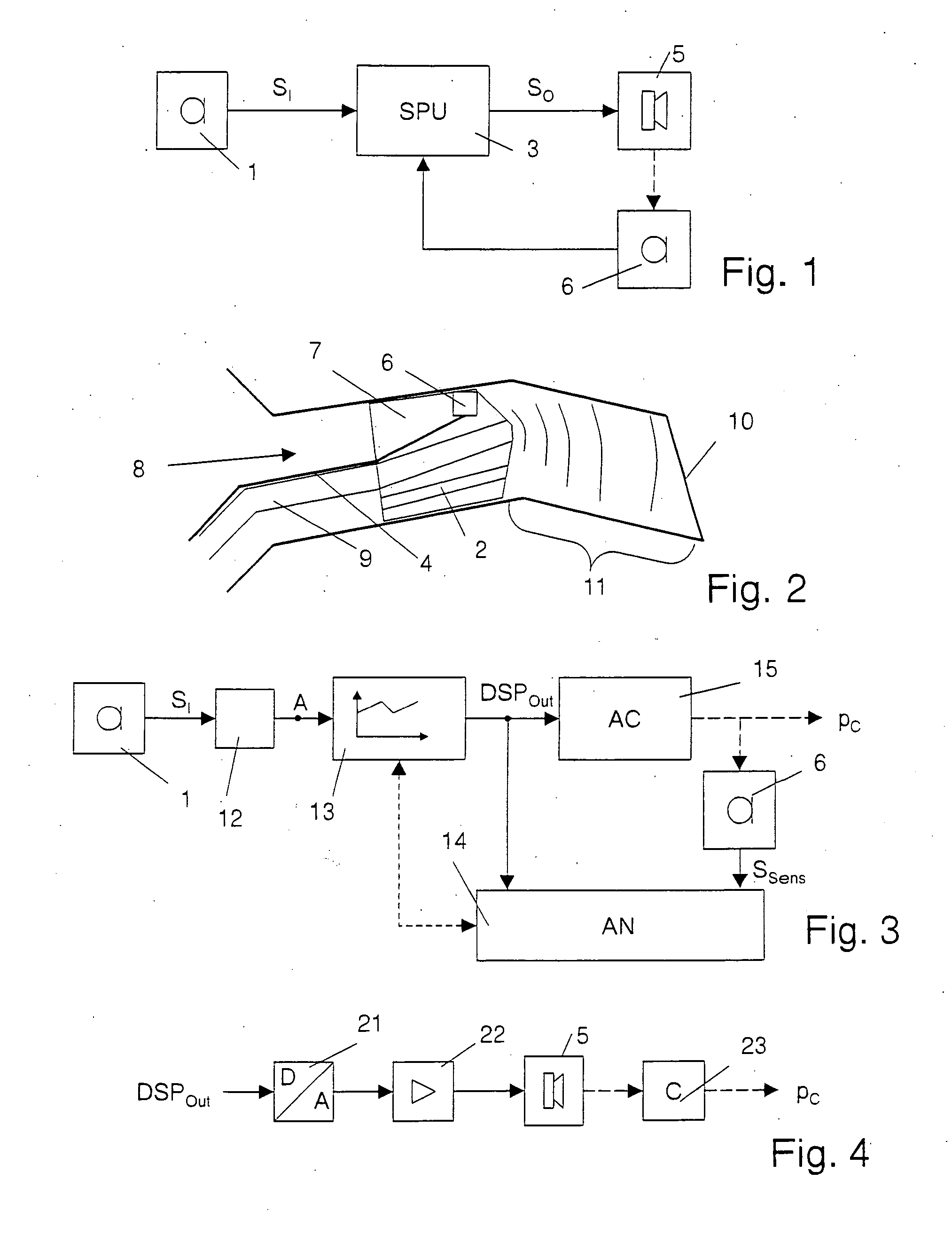
[0069] In FIG. 2, very schematically an ear canal 8 with an inserted in-the-ear-canal component, namely an otoplastic 7, of a behind-the-ear hearing instrument is illustrated. In general, an in-the-ear-canal component or an in-the-ear component of a hearing instrument in the context of this application is also called earpiece. The sound output signal is guided from the receiver to an interior of the ear canal 8 by means of a sound conducting tube 9 held by the otopla...


PUM


Abstract

According to the invention, a hearing instrument comprising at least one inner microphone operable to determine a sensing signal representative of an acoustic signal at a position in front of the user's eardrum—which may be an acoustic signal at a position between an ITE (or ITC or CIC) hearing instrument and the eardrum or between an earpiece and the eardrum—is used. In accordance with the invention, in front of the eardrum an acoustic signal is produced. The inner microphone creates a sensing signal representative of the acoustic signal, and the signal processing unit of the hearing instrument determines a characteristic of the user's ear canal based thereon and memorizes values indicative of the characteristic. According to a preferred embodiment, the characteristic is an acoustic coupling transfer characteristic, which is determined based on a comparison of a signal representative of the output signal of the signal processing unit's digital signal processing stage and the sensing signal. In contrast to the state of the art, no control loop is necessary to adapt the gain to the ear canal characteristic, but the memorized values may be used therefor.

Description

FIELD OF THE INVENTION [0001] The invention is in the field of hearing instruments. It more particularly relates to a method of obtaining a characteristic of acoustical circumstances in an ear canal of a user, to a hearing instrument, and to a method of fabricating a hearing instrument. BACKGROUND OF THE INVENTION [0002] The acoustical output of a hearing instrument as perceived by the user depends on the environment of the hearing instrument, especially on the ear canal properties. Conventionally, for modeling the effective gain provided by a hearing instrument placed in an ear canal, measurements in a so-called “2 cc coupler” are used. However, this model system merely provides an influence of an average ear canal on the effective gain provided by a hearing instrument. The accuracy of such a model system is limited. The difference between the signal level in the real ear and the level in the 2 cc coupler is often called “Real Ear to Coupler Difference” RECD. [0003] As a consequenc...

Claims


Application Information

Patent Timeline
IPC IPC(8): H04R25/00
CPCH04R25/505
Inventor STIRNEMANN, ALFRED
Owner PHONAK
Why Eureka
Try Eureka