
Layer 2 virtual switching environment

a virtual switching environment and virtual switch technology, applied in the field of virtual switch engines for communication devices, can solve the problems of not addressing stackable switches, difficulty in internal set-up of logical pathways, different virtual switch requirements, etc., and achieve the effect of reducing the cost per virtual switch and reducing the inter-communication cost in memory

Inactive Publication Date: 2007-02-15
NEXTHOP TECH INC
View PDF2 Cites 236 Cited by
  • Summary
  • Abstract
  • Description
  • Claims
  • Application Information

AI Technical Summary

Benefits of technology

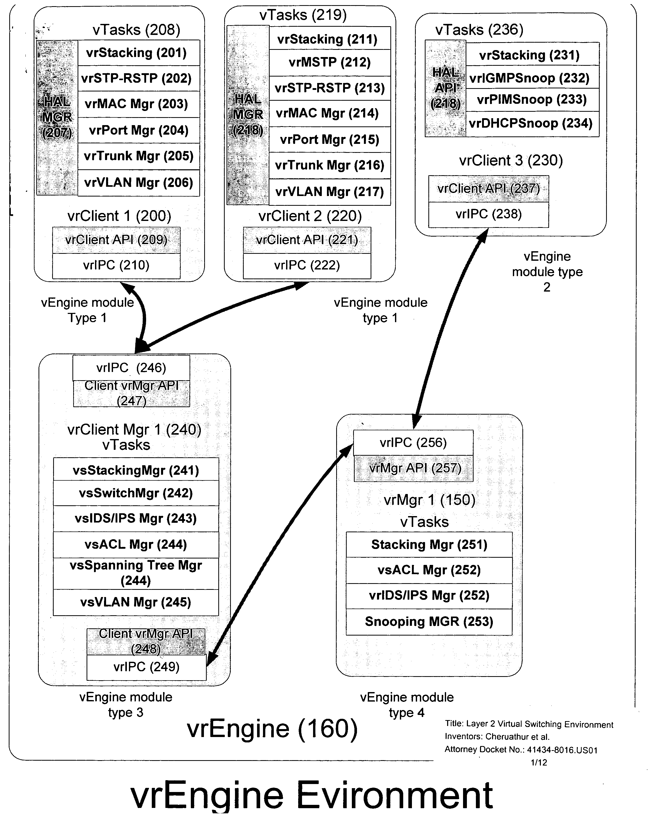
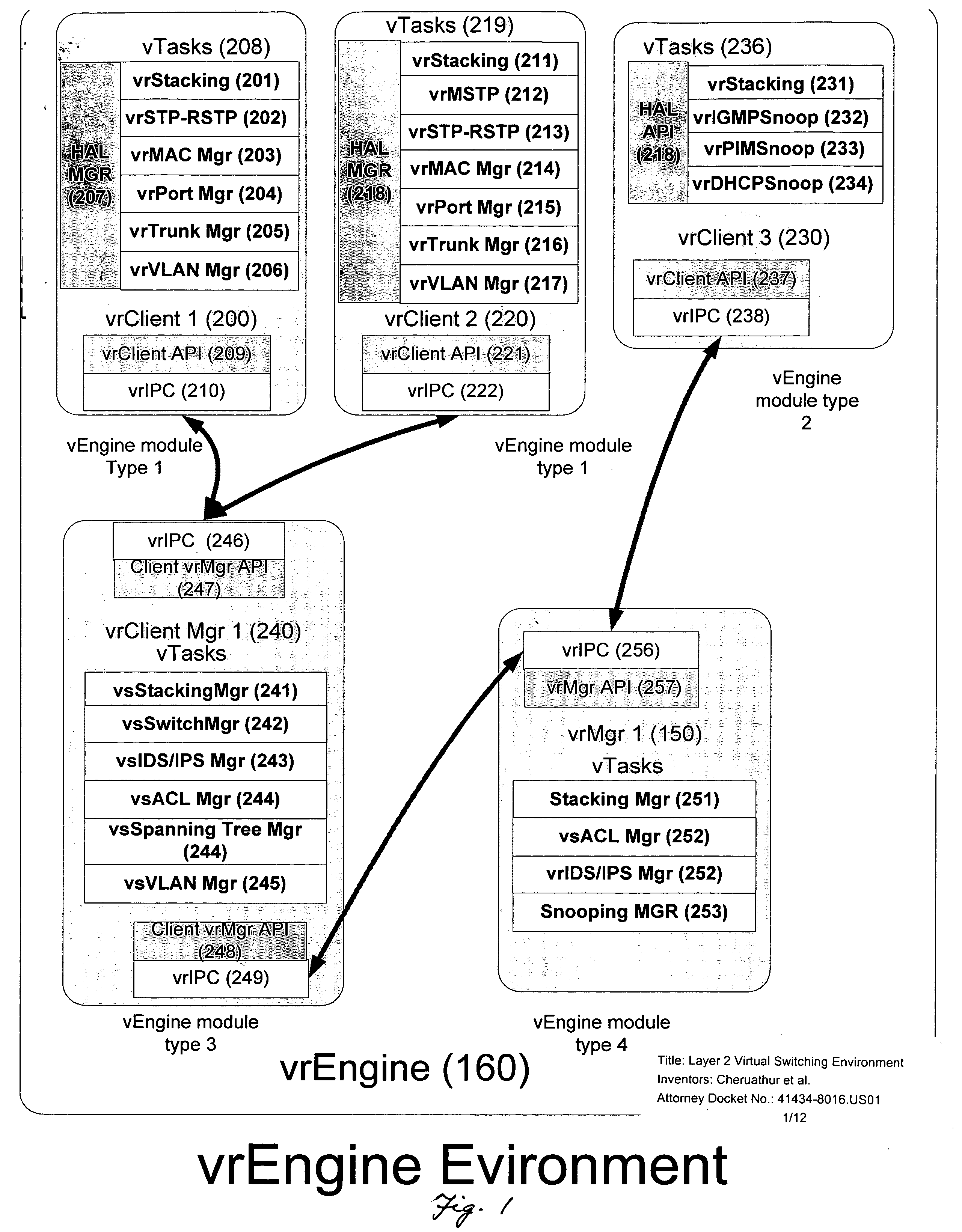
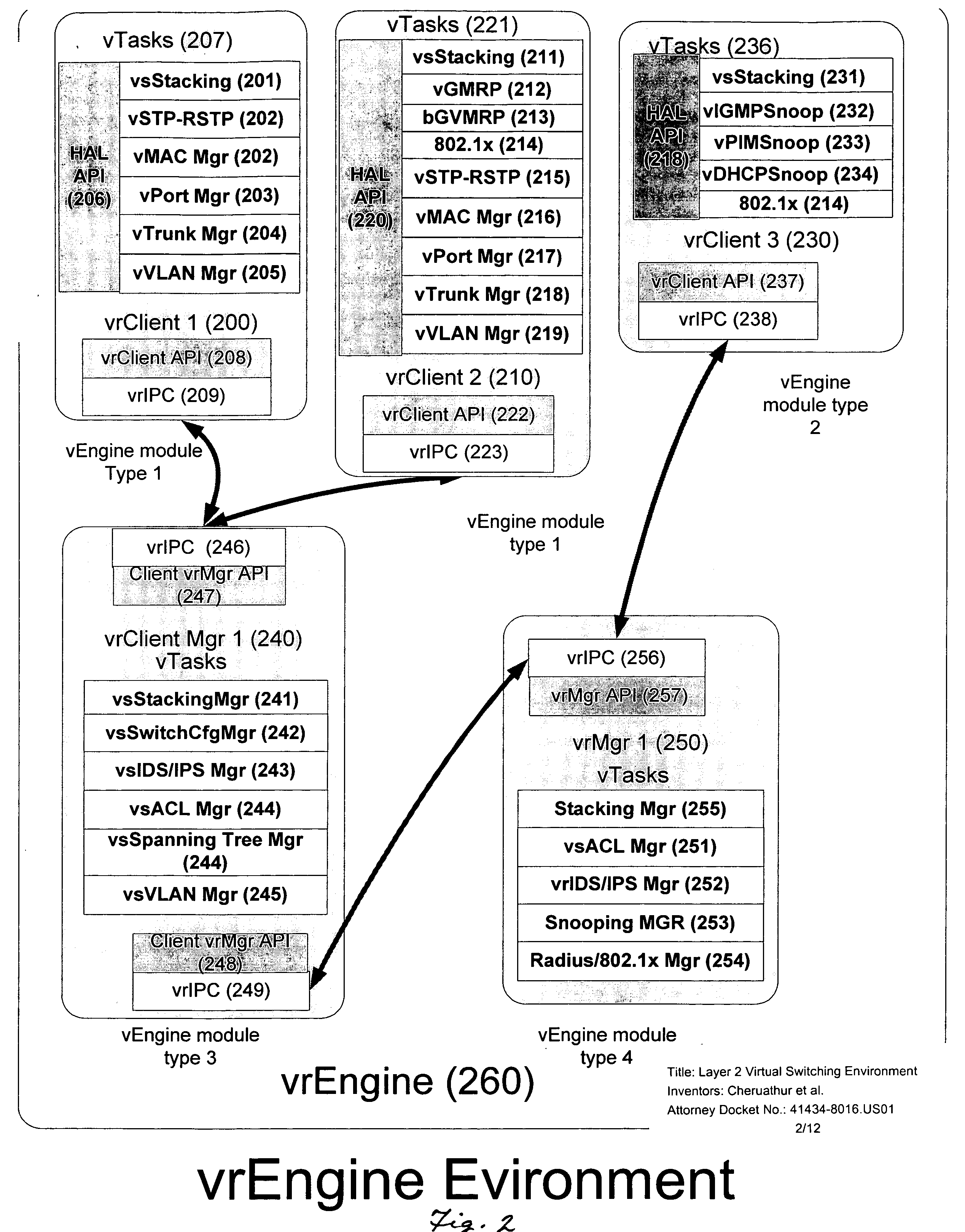
[0085] This invention is a method for a Virtual Communication Environment to support virtual switching engines (VSE) for layer 2 switches. The virtual layer 2 switching engines allow many virtual switches to be created in a CPU or across multiple CPUs in switching hardware. The virtual switch engines (VSE) with reduces the inter-communication costs in memory, CPU, inter-process bandwidth, and fabric bandwidth. This reduction in the cost per Virtual Switch device allows either more virtual switches to be contained within a control plane or more applications per switch control plane.

Problems solved by technology

Network software has constraints on timing, data throughput and processing required that make virtualization requirements different than normal PC management.
This presents some difficulties to internal set-up of a logical pathway within a switch or a stackable switch.
These protocols do not address stackable switches or virtual stackable switches.

Method used


Image

  • Layer 2 virtual switching environment
  • Layer 2 virtual switching environment
  • Layer 2 virtual switching environment

Examples


second embodiment

[0164] this invention allows the first stage of bring up to be one stage: [0165] Stage 1: Link state path vector hello serves as a light-weight hello, and [0166] Stage 2: Upon exchanging secure hello, the two VSE stackable switches immediately exchange databases and calculate paths based on pre-shared policy.

third embodiment

[0167] this invention allows initial distribution of FIB information between two switches in a master-slave relationship: [0168] Stage 1: light hello protocol such as IETF BFD to determine if the two processes can see one another, [0169] Stage 2: Secure Link-State Path Vector hello exchange and Master-Slave status set between two peers. [0170] Stage 3: Link State Path Vector queues the FIB synchronization protocol to run in parallel to update current state of FIB from master to the slave, [0171] Stage 4: Link State Path Vector passes topology information to / from the master and slave; FIB information is restricted to the master.

[0172] As these embodiments indicate, the virtual stacking protocol runs with a link state path vector algorithm allowing hierarchy and opacity at certain points in the hierarchy. The opacity allows a virtual switch participating as a master at one level to be a slave at the next higher level. The virtual switch stacking algorithms can allow opacity to treat ...


PUM


Abstract

A Virtual Communication Environment to support virtual switching engines for layer 2 switches is described. The virtual layer 2 switching engines allow many virtual switches to be created in a CPU or across multiple CPUs in switching hardware. The virtual switch engines reduce the inter-communication costs in memory, CPU, inter-process bandwidth, and fabric bandwidth. This reduction in the cost per Virtual Switch device allows either more virtual switches to be contained within a control plane or more applications per switch control plane.

Description

CLAIM OF PRIORITY AND CROSS REFERENCE TO RELATED APPLICATIONS [0001] This application claims priority to U.S. Provisional Patent Application No.: 60 / 649,482 entitled LAYER 2 VIRTUAL SWITCHING ENVIRONMENT, filed Feb. 2, 2005, inventors Hares, et al., attorney reference: 41434-8016.US00; U.S. Provisional Patent Application No. 60 / 650,435 entitled VIRTUAL SWITCHING ENVIRONMENT, filed Feb. 3, 2005, inventors Hares, et al., attorney reference: 41434-8017.US00; U.S. Utility Patent Application No.: 11 / 121,162 entitled VIRTUALIZATION OF CONTROL SOFTWARE FOR COMMUNICATION DEVICES, filed May 2, 2005, inventors Hares, et all, attorney reference 41434-8009.US01; and U.S. Provisional Patent Application No. 60 / 567,358, filed Apr. 30, 2004, entitled VIRTUALIZATION OF CONTROL SOFTWARE FOR COMMUNICATION DEVICES, inventors Hares, et al., attorney reference: 41434-8009.US00, all of which are hereby incorporated by reference in their entirety.FIELD OF INVENTION Virtualization engines for software for ...

Claims


Application Information

Patent Timeline
Patent Type & Authority Applications(United States)
IPC IPC(8): H04J1/00H04J3/04
CPCH04L45/00H04L49/70H04L49/351H04L45/245H04L45/76
Inventor HARES, SUSANCHEN, JOSEPHLEE, CHOONMANGHIRMALAN, RAVI
Owner NEXTHOP TECH INC
Learn More