
Image detecting module

a technology of image detection and module, applied in the field of image detection modules, can solve the problems of increasing the volume of the camera, limited compensation effect of the method, and reducing the image quality

Active Publication Date: 2007-02-15
ASIA OPTICAL INT LTD
View PDF2 Cites 7 Cited by
  • Summary
  • Abstract
  • Description
  • Claims
  • Application Information

AI Technical Summary

Benefits of technology

[0031] Because the invention changes the position of the image detecting unit with respect to the optical axis rather than adjusting the lens position, image quality is affected. Further the pair of coils and a pair of magnets moving the image detecting unit resulting in the element having small volume, allowing reduced camera size.

Problems solved by technology

This compensation method has limited compensation effect and may reduce image quality.
As the CCD, however, is heavier than a single lens, a large piezoelectric element is needed, increasing the volume of the camera.

Method used


Image

  • Image detecting module
  • Image detecting module
  • Image detecting module

Examples


Embodiment Construction

[0023] Before the description, it is noted that location language, such as first direction X, second direction Y, or third direction Z, is based on the coordinate of each individual figure, and the first direction X, second direction Y, and the third direction Z are orthogonal.

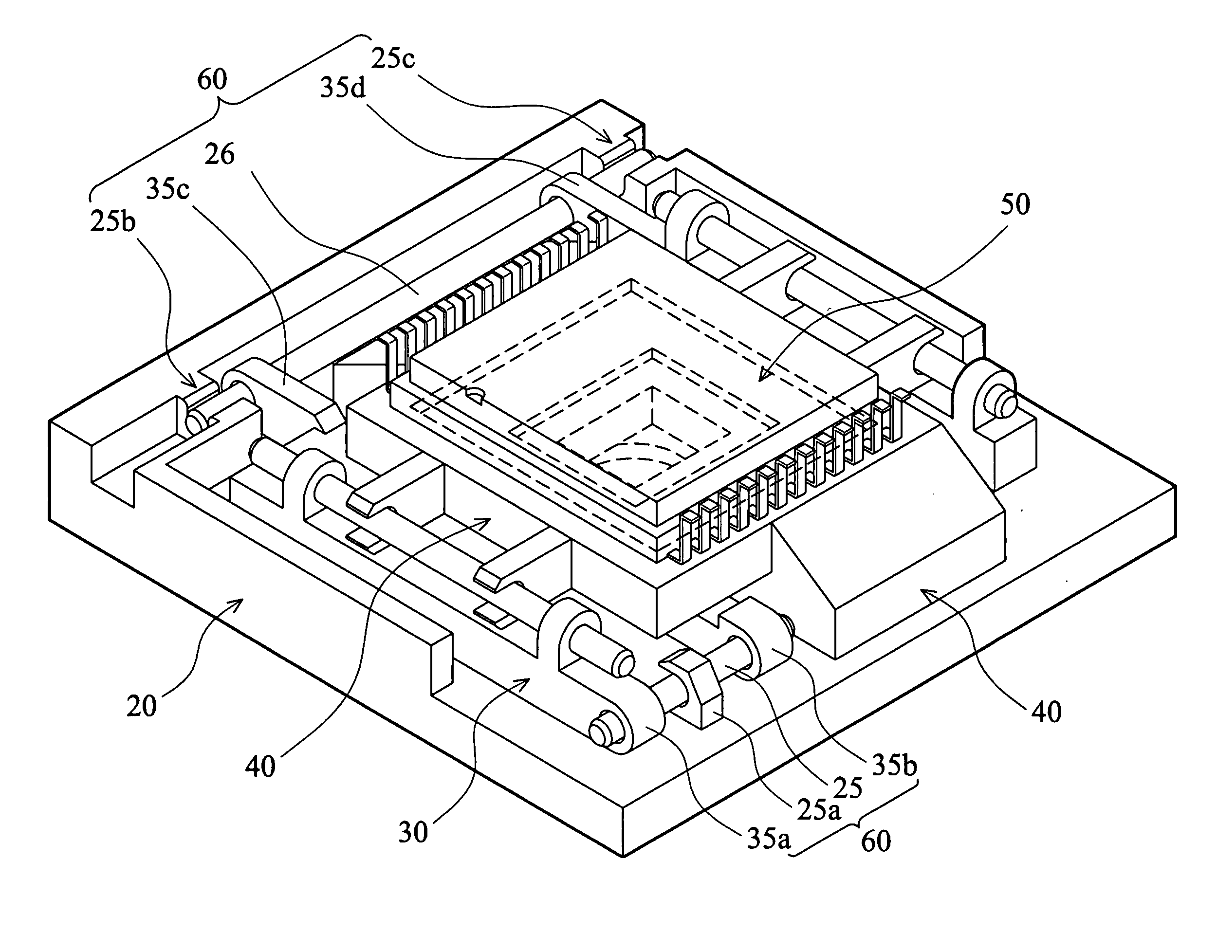
[0024] Referring to FIG. 3, an embodiment of an image detecting module of the invention comprises a base 20 with a hollow portion 29, a seat 30 disposed in the hollow portion 29, a movable plate 40 disposed in the seat 30, and an image detecting unit 50 (such as a CCD)disposed on the movable plate 40. The sensing surface of the image detecting unit 50 faces opposite the third direction Z.

[0025] Referring to FIG. 4, the base 20 comprises a pair of first magnets 21 and 22, a pair of second magnets 23 and 24 and a pair of parallel first shafts 25 and 26. The first magnet 21 and 22 are disposed parallel on two sides of the hollow portion 29. The N pole and S pole of the first magnet 21 are disposed along the fir...


PUM


Abstract

An image detecting module. The image detecting module comprises a base, a seat movably disposed on the base, an image detecting unit disposed on the seat, a first guide member by which the seat is joined to the base, moving relative to the base in a first direction, a first coil disposed on either the base or the seat, a first magnet disposed on either the base or the seat and opposite to the first coil, and a first Hall element disposed on either the base or the seat and adjacent to the first coil. A magnetic force is generated between the first coil and the first magnet by providing a voltage to the first coil, thereby moving the seat in the first direction along the first guide element.

Description

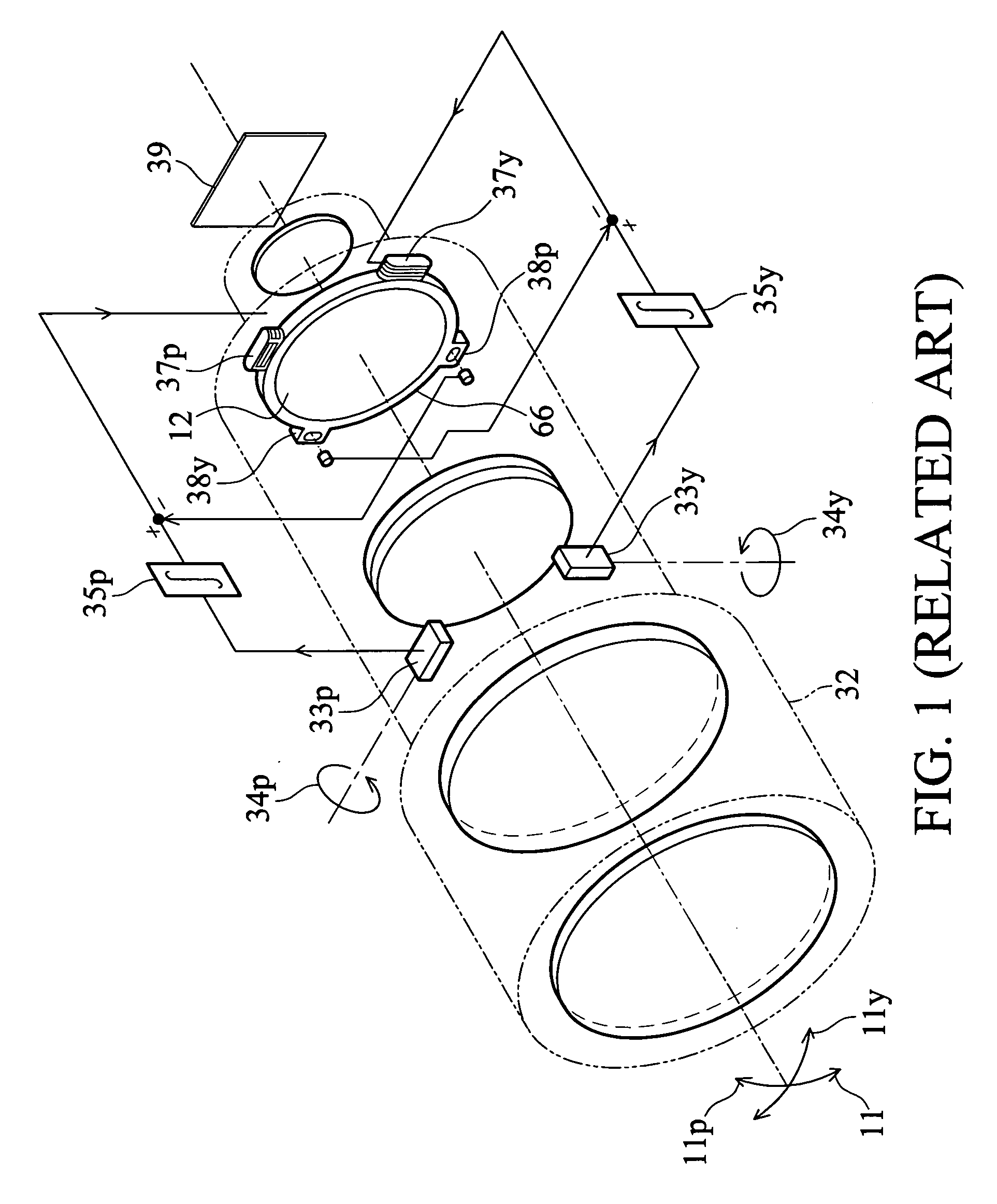
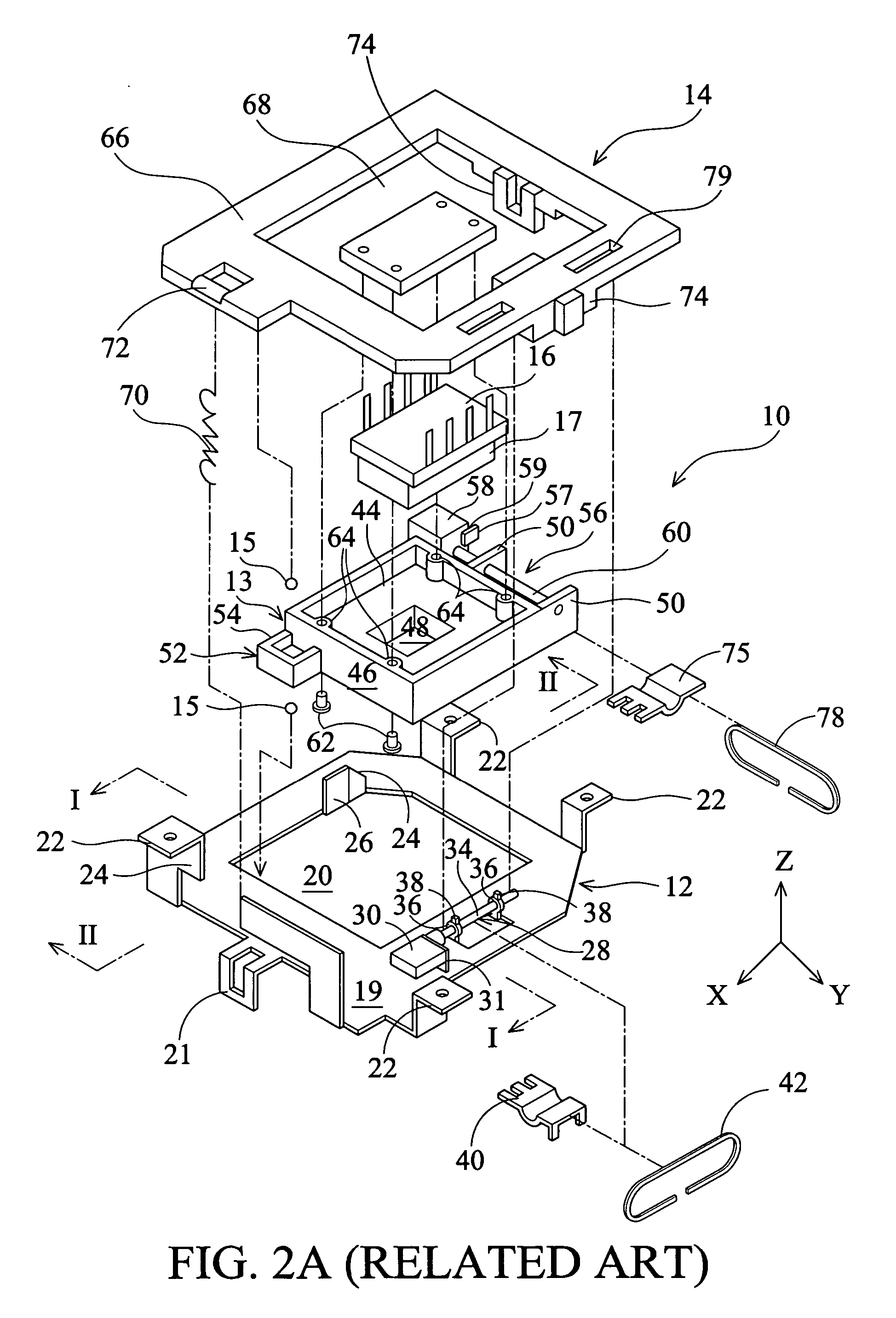
BACKGROUND [0001] The invention relates to an image detecting module, and in particular to an image detecting module having an image detecting unit with 2-dimensional motion. [0002] Referring to FIG. 1, U.S. Pat. No. 5,266,988 discloses an image shake suppressing device for a camera. The image shake suppressing device is mounted in a lens. When the camera is used, an angular velocity meter measures the angular velocity of the moving camera and provides the measured data to a circuit to drive a driving part moving the lens in a direction of a vertical optical axis, thereby compensating or suppressing blurring due to vibration of the camera. [0003] Because the lens, however, is moved in a vertical optical axis, the MTF value thereof is reduced. This compensation method has limited compensation effect and may reduce image quality. [0004] Referring to FIGS. 2A and 2B, Japan patent No. 3551174 discloses a moving mechanism. The moving mechanism employs piezoelectric elements to drive an i...

Claims


Application Information

Patent Timeline
Patent Type & Authority Applications(United States)
IPC IPC(8): H01J3/14H04N23/40
CPCG02B27/646H04N5/2253H04N5/23287H04N5/23258H04N5/23248H04N23/54H04N23/68H04N23/6812H04N23/687
Inventor HSIEH, WEN-HUNGLIAO, JIAN-CHAOTSAI, CHING-JUNG
Owner ASIA OPTICAL INT LTD
Learn More