
Medical diagnostic and communication system

a communication system and diagnostic technology, applied in the field of medical diagnostic and communication system, can solve the problems of not being able to provide enhanced services to mobile users over a wide area, not having readily and widely accessible cellular and cellular interconnections, and many wide bandwidth applications and services that are rapidly evolving, etc., to achieve the effect of improving performance, high speed operation, and extending coverag

Inactive Publication Date: 2007-02-08
FEHER KAMILO
View PDF99 Cites 114 Cited by
  • Summary
  • Abstract
  • Description
  • Claims
  • Application Information

AI Technical Summary

Benefits of technology

"The patent text discusses the need for multi-use wireless communication devices that can access a wide range of services and applications. The technical effects of the patent include the development of multi-mode, multi-standard interoperable technologies that integrate the capabilities of cellular, infrared, satellite, and WLAN systems. The patent also describes adaptable or agile systems that can adapt to different standards and frequencies, as well as cross-correlated structures and features. Overall, the patent aims to provide efficient and effective multi-use communication devices that can offer enhanced services to mobile users over a wide area."

Problems solved by technology

Hence, many wide bandwidth applications and services that are rapidly evolving, for example, on the Internet, have not to date readily and widely accessible cellular and cellular interconnections to mobile wireless users via wireless local area networks (WLAN) and / or other wideband networks.
However, the WLAN systems only provide short range coverage, are not widely deployed, or do not provide for user mobility and hence are not generally suitable of providing enhanced services for mobile users over a wide area.

Method used


Image

  • Medical diagnostic and communication system
  • Medical diagnostic and communication system
  • Medical diagnostic and communication system

Examples


Embodiment Construction

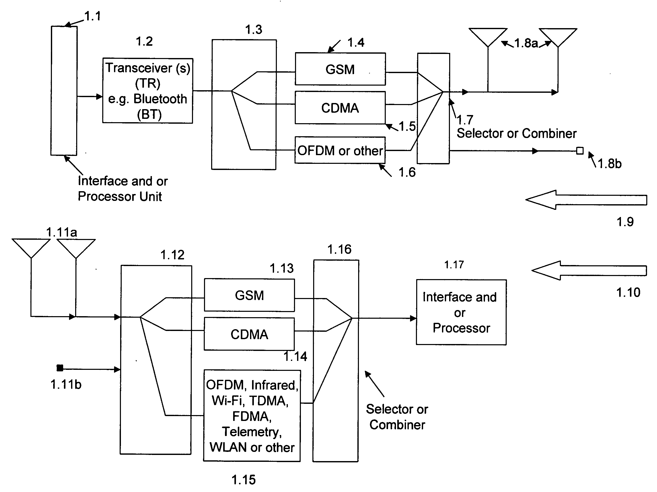
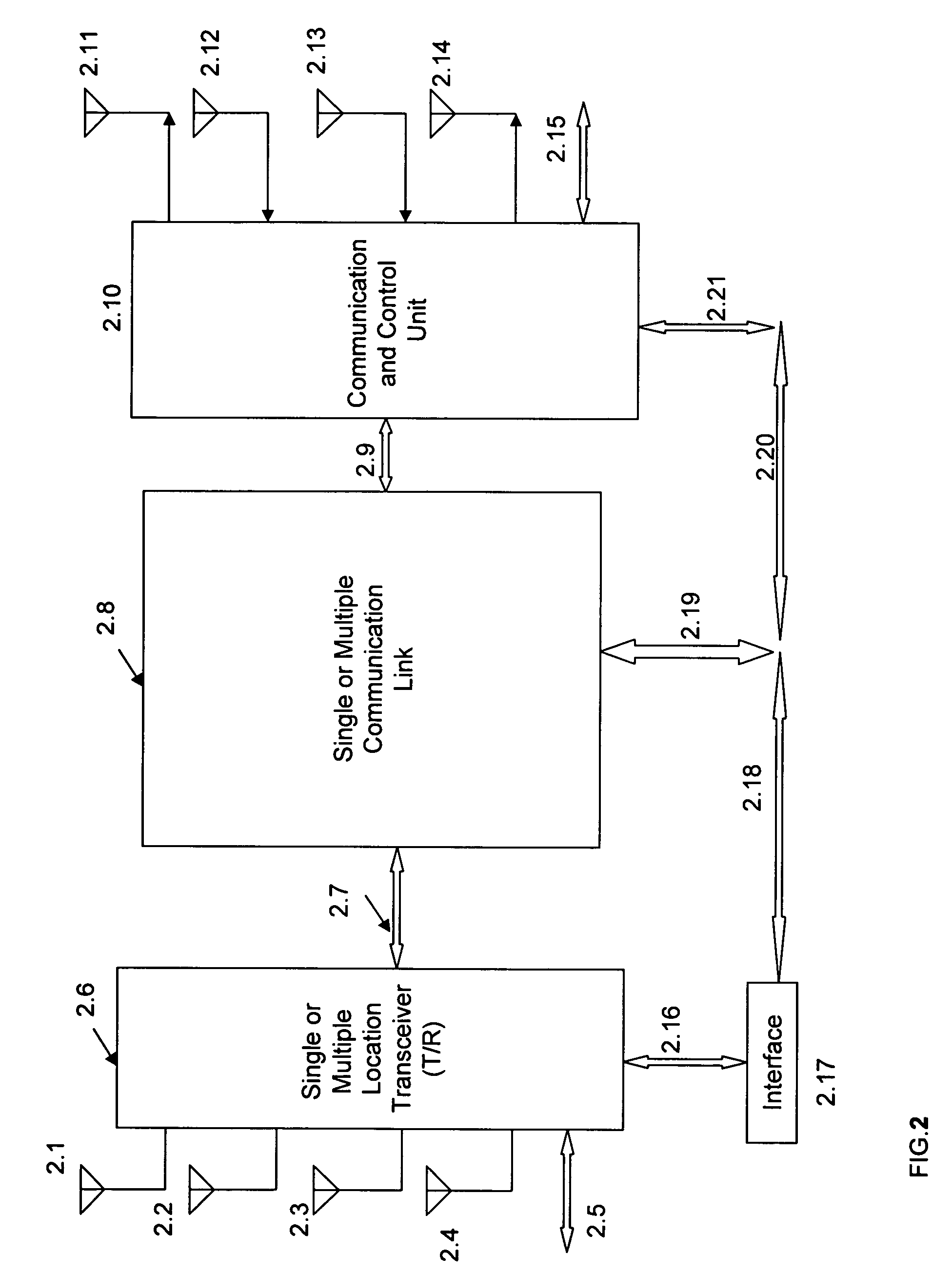
[0136] In this section, the present invention is more fully described with reference to the accompanying drawings in which preferred embodiments of the invention are shown. This invention may, however, be embodied in many different forms and should not be construed as limited to the illustrated embodiments set forth herein. Rather, these embodiments are provided so that this disclosure will be thorough and complete, and will fully convey the scope of the invention to those skilled in the art.

[0137] One or more devices (alternatively designated as units, elements, systems, terminals, devices, leads or connections) are optional in the embodiments. The elements may be interconnected and or used in various configurations. In the figures and relevant descriptions of the figures, as well as in the specifications of this disclosure, some of the units or elements are optional and are not required for certain applications, embodiments and or structures. In this document the term “signal” ha...


PUM


Abstract

Cardiac stimulation device and wireless communication system, without magnetic detection or magnetic control of the heart pacemaker parameters, having leads for carrying stimulating pulses to and or from one or more electrodes located in a heart and a pulse generator configured to generate stimulation pulses. In certain embodiments and environments the heart pacemaker could operate in an emergency room, even during Magnetic Resonance Imaging (MRI) diagnostic studies. A processor for connection of the stimulating pulses to and / or from one or more spread spectrum transmitter-receiver (T / R) circuits and / or from a signal processing network for receiving said stimulation pulses and for providing cross-correlated in-phase and quadrature-phase baseband signals. One or more modulators and demodulators for transmission and / or reception of one or more spread spectrum and / or cross-correlated signals.

Description

RELATED CO-PENDING U.S. PATENT APPLICATIONS [0001] The following three (3) related U.S. patent applications, submitted by Applicant / Inventor Kamilo Feher, are co-pending: [0002] U.S. utility patent application Ser. No. ______, Ref. No. (56), entitled “Location finder, tracker, communication and remote control system”, submitted to the United States Patent and Trademark Office (USPTO) on Aug. 3, 2005. [0003] U.S. utility patent application Ser. No. ______, Ref. No. (57), entitled “Medical diagnostic and communication system”, submitted to the United States Patent and Trademark Office (USPTO) on Aug. 3, 2005. [0004] U.S. utility patent application Ser. No. ______, Ref. No. (58), entitled “Multimode communication system”, submitted to the United States Patent and Trademark Office (USPTO) on Aug. 3, 2005. CITED REFERENCES—PARTIAL LIST OF RELEVANT LITERATURE [0005] Several references, including issued United States patents, pending US patents, and other references are identified herein t...

Claims


Application Information

Patent Timeline
Patent Type & Authority Applications(United States)
IPC IPC(8): A61N1/362H04W4/90H04W64/00H04W88/06
CPCH04W64/00A61B5/0015H04W88/06G16H10/60G16H15/00H04W4/90H04B7/18504H04W4/025H04B7/2628H04W12/06H04W4/023Y02A90/10H04W12/79H04L27/2649H04B1/709H04B2201/70715H04B2201/70716H04L27/2017H04L27/2627H04L1/0003H04L5/1453H04B1/707H04L5/0007H04B1/1036H04B1/69H04B7/04H04M7/006H04W88/02A61B5/0022A61B5/01A61B5/024A61B5/14532H04J11/00H04L27/2071
Inventor FEHER, KAMILO
Owner FEHER KAMILO
Learn More