
RF matching network of a vacuum processing chamber and corresponding configuration methods

a vacuum processing chamber and matching network technology, applied in the field of rf matching network, can solve the problems of large loss of energy, overheating or even damage of the input circuit, and the capacitance impedance of the vacuum processing chamber, so as to reduce or avoid the heating of the circuit, reduce the parasitic capacitance of the inductor, and improve the energy input efficiency.

Active Publication Date: 2007-02-08
ADVANCED MICRO FAB EQUIP INC CHINA
View PDF8 Cites 16 Cited by
  • Summary
  • Abstract
  • Description
  • Claims
  • Application Information

AI Technical Summary

Benefits of technology

The present invention provides a vacuum processing chamber that can overcome the problems associated with the isolation between multiple RF generators. The invention includes an RF matching network that includes circuits with high impedance at the output port relative to the input port at the second frequency, which helps prevent heating or burning up of the RF generators. The method of supplying RF energy to the vacuum processing chamber includes connecting a first frequency RF input port to a first frequency RF generator, and connecting a second frequency RF input port to a second frequency RF generator. The method also includes providing an output port that outputs the energy of multiple RF generators to the vacuum processing chamber. The technical effects of the invention include improved safety and efficiency in vacuum processing.

Problems solved by technology

One difficulty which arises is that the vacuum processing chamber has a capacitive impedance which exists between the upper and lower electrodes.
This usually causes the input circuit to overheat or even become damaged.
As a first matter, direct filtering of energy causes a great loss of energy, and further reduces the input efficiency.
Secondly, filtering of energy will typically cause the notch or filter to heat up.
Moreover, large filters are needed for the filtering of high power energy, thus increasing the volume and weight of the resulting equipment, and the costs associated with the design and manufacturing of the same equipment.

Method used


Image

  • RF matching network of a vacuum processing chamber and corresponding configuration methods
  • RF matching network of a vacuum processing chamber and corresponding configuration methods
  • RF matching network of a vacuum processing chamber and corresponding configuration methods

Examples


Embodiment Construction

[0025] This disclosure of the invention is submitted in furtherance of the constitutional purposes of the U.S. Patent Laws “to promote the progress of science and useful arts” (Article 1, Section 8).

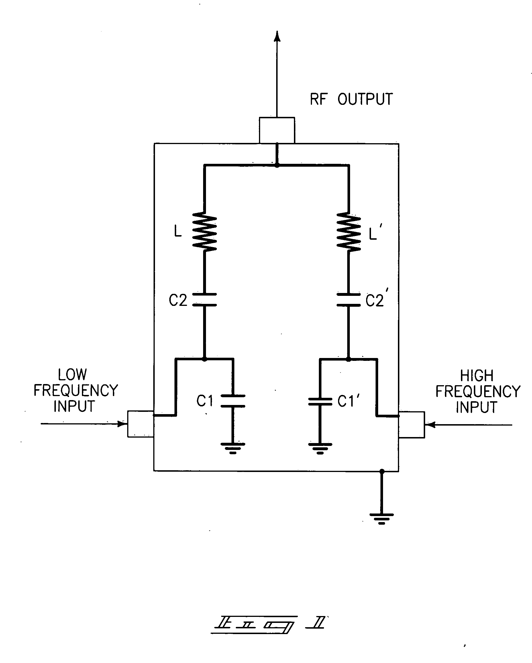
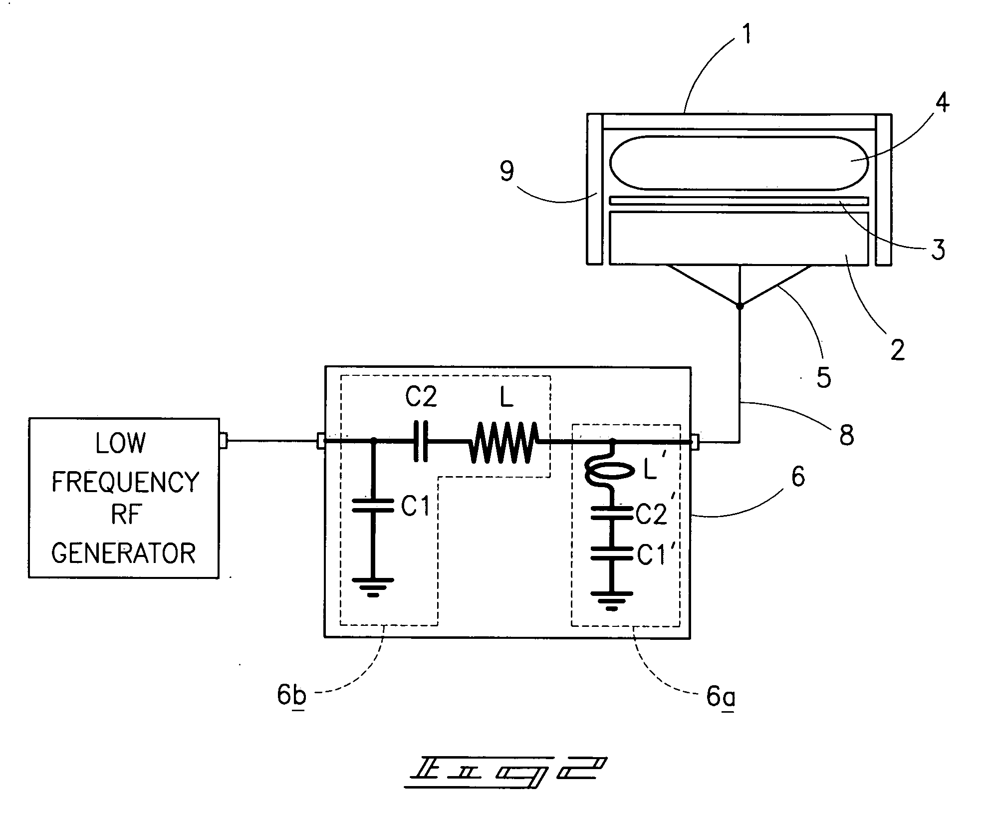
[0026]FIG. 1 is a schematic diagram of the structure of a RF matching network for use with a vacuum processing chamber of the present invention. As shown in the figure, this embodiment has two RF inputs, one being the high frequency input part, the other being a low frequency input part. There are overall three ports in the RF matching network, and wherein two are input ports, namely the high frequency input port connected to the high frequency RF generator, and the low frequency input port connected to the low frequency RF generator, and an RF output port outputting the energy of multiple RF generators to the vacuum processing chamber. The RF matching network of the vacuum processing chamber can be divided into a low frequency part and a high frequency part, and wherein these two parts...


PUM


Abstract

A RF matching network is described, and which includes a 1st to nth RF generators, and wherein each RF generator has a different frequency, and wherein the frequencies of the 1st to the nth RF input ports decline in sequence, and wherein between the ith frequency RF input port, and the output port is a ith circuit, which has a high impedance at the output port to all RF generator frequencies other than the ith frequency; and wherein the ith circuit, when connected to a RF generator with the ith frequency, and wherein measuring from the output port to the ith circuit, the ith circuit has a first impedance at the ith frequency; and when measuring from the output port in the opposite direction to the ith circuit, the ith circuit has a second impedance at the ith frequency; and wherein the first impedance is a substantial conjugate match of the second impedance.

Description

RELATED PATENT DATA [0001] This application claims priority from Chinese Patent Application Serial No. 200510028564.7, and which was filed on Aug. 5, 2005. TECHNICAL FIELD [0002] The present invention relates to the field of semiconductor and / or integrated circuit manufacturing, and more specifically to a RF matching network which is useful with a vacuum processing chamber, and corresponding methods of employing same. BACKGROUND OF THE INVENTION [0003] The operation of a vacuum processing chamber are well known. In this regard, reaction gases are introduced to the vacuum processing chamber, and then RF energy is delivered into the vacuum processing chamber. This RF energy activates or energizes the reaction gas, thereby forming a resulting plasma in the vacuum processing chamber. This plasma is then used to process a semiconductor workpiece which is placed in same. Heretofore, one of the previous practices was to input RF energy of a single frequency onto the lower electrode of the ...

Claims


Application Information

Patent Timeline
Patent Type & Authority Applications(United States)
IPC IPC(8): H03H7/38
CPCH01J37/32082H05H1/46H03H7/40H01J37/32183
Inventor XIA, YAOMIN
Owner ADVANCED MICRO FAB EQUIP INC CHINA
Learn More