
Manufacturing process for hydrogen pressure tank

a technology of hydrogen pressure tank and manufacturing process, which is applied in the direction of manufacturing tools, other domestic articles, vessel construction details, etc., can solve the problems of limited effect of temperature drop, affecting the gas tight performance of the tank, and difficult production of materials that can seal hydrogen in this temperature range. achieve the effect of increasing the integrity of the seal

Active Publication Date: 2007-02-08
GM GLOBAL TECH OPERATIONS LLC
View PDF3 Cites 14 Cited by
  • Summary
  • Abstract
  • Description
  • Claims
  • Application Information

AI Technical Summary

Benefits of technology

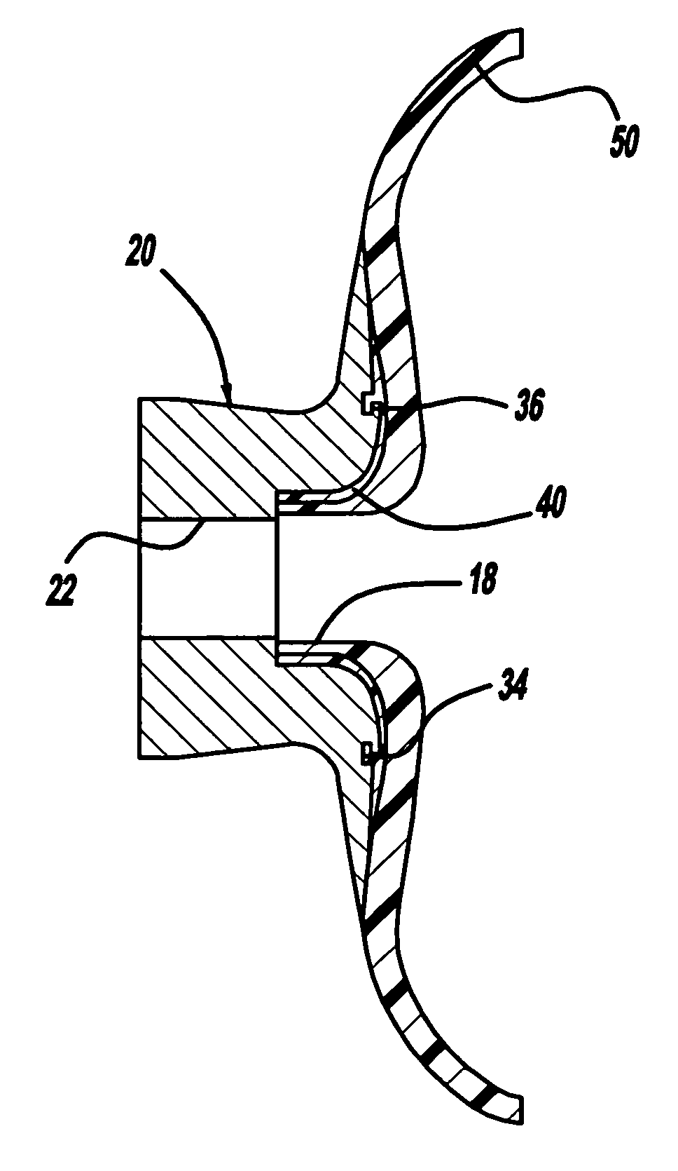
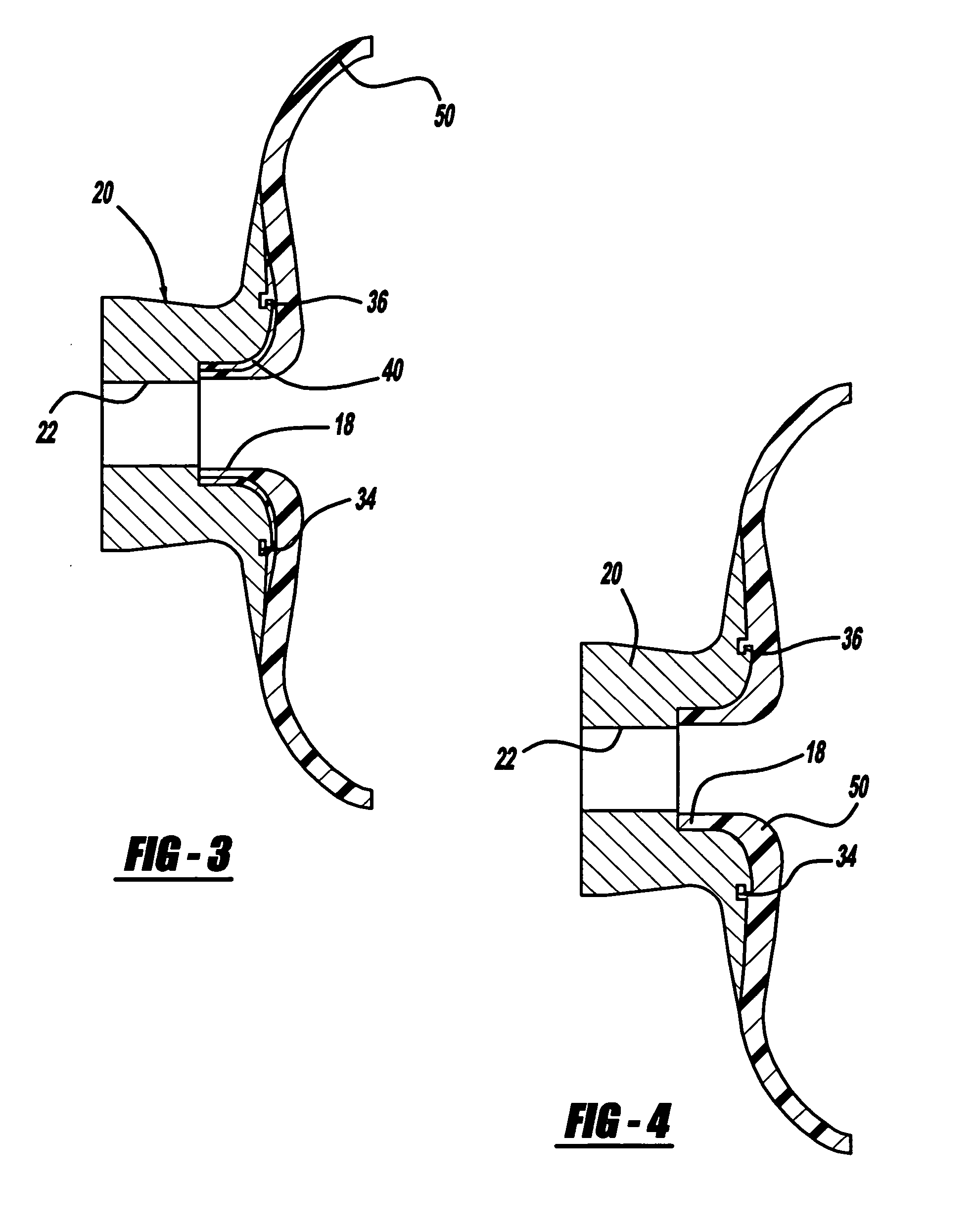
[0013] In accordance with the teachings of the present invention, a process for manufacturing a compressed gas tank is disclosed that includes a combination of an injection molding process and a rotomolding process. In a first step, a boss to be positioned in the opening of an outer structural layer of the tank is provided and a thin portion of a tank liner is injection molded to the boss so that a channel within the boss is filled with the liner material to increase the seal integrity between the boss and the liner. Once the liner material has hardened, the surface of the injection molding liner portion is cleaned. Next, a rotomolding process is performed to mold the remaining portion of the liner. During the rotomolding process, the injection molded portion of the liner is melted to be part of the liner made during the rotomolding process.

Problems solved by technology

The effect of the decrease in the temperature will be limited because heat is transferred from the environment into the tank.
Further, when the tank is being filled with hydrogen, the temperature of the hydrogen can increase to 80° C. due to the compression of the hydrogen inside of the tank, providing a temperature swing of −80° C. to 80° C. The materials that can seal hydrogen in this temperature range are difficult to produce.
If the temperature of the hydrogen within the tank decreases beyond a certain temperature, such as −80° C. around the liner and −40° C. at the tank seals, including O-rings and other sealings, the materials become brittle and possibly damaged, affecting the tank's gas tight performance.
Therefore, there are limits as to how fast hydrogen and / or for how long hydrogen can be removed from the compressed tank in a fuel cell system.
The rotomolding process is not conducive for filling small gaps, and therefore the channel 34 may not completely fill with the liner material during the rotomolding process, thus affecting the sealing properties at this location in the tank 10.
However, because of the size of the tank 10 and the time required to injection mold, injection molding the liner 14 is not a cost effective process.

Method used


Image

  • Manufacturing process for hydrogen pressure tank
  • Manufacturing process for hydrogen pressure tank
  • Manufacturing process for hydrogen pressure tank

Examples


Embodiment Construction

[0019] The following discussion of the embodiments of the invention directed to a process for manufacturing a compressed hydrogen tank is merely exemplary in nature, and is in no way intended to limit the invention or its applications or uses. Particularly, the process has an application for making a compressed hydrogen tank for storing hydrogen in a fuel cell system. However, as will be appreciated by those skilled in the art, the process has application to produce tanks other than compressed hydrogen tanks.

[0020] The following discussion of the invention discloses a process for manufacturing a compressed hydrogen gas tank to better provide seal integrity between a liner of the tank and a boss of the tank of the type discussed above with reference to FIG. 1. The discussion of the invention below uses the same reference numerals for the tank 10 above solely for ease of understanding. Generally, the process includes a two-part step for molding the liner 14 where an injection molding...


PUM

PropertyMeasurementUnit
pressureaaaaaaaaaa
temperatureaaaaaaaaaa

Abstract

A process for manufacturing a compressed gas tank that includes a combination of an injection molding process and a rotomolding process. In a first step, a boss to be positioned in the opening of an outer structural layer of the tank is provided and a thin portion of the liner is injection molded to the boss so that a channel within the boss is filled with the liner material to increase the seal integrity between the boss and the liner. Once the liner material is hardened, the surface of the injection molding liner portion is cleaned. Next, a rotomolding process is performed to mold the remaining portion of the liner to the boss. During the rotomolding process, the injection molded portion of the liner melts to be part of the liner made during the rotomolding process.

Description

BACKGROUND OF THE INVENTION [0001] 1. Field of the Invention [0002] This invention relates generally to a manufacturing process for a compressed hydrogen tank and, more particularly, to a manufacturing process for a compressed hydrogen tank that includes injection molding a portion of a liner of the tank to fill a sealing gap in a tank boss and then rotomolding the rest of the liner thereafter. [0003] 2. Discussion of the Related Art [0004] Hydrogen is a very attractive fuel because it is clean and can be used to efficiently produce electricity in a fuel cell. The automotive industry expends significant resources in the development of hydrogen fuel cell systems as a source of power for vehicles. Such vehicles would be more efficient and generate fewer emissions than today's vehicles employing internal combustion engines. [0005] Typically hydrogen is stored in a compressed gas tank under high pressure on the vehicle to provide the hydrogen necessary for the fuel cell system. The pres...

Claims


Application Information

Patent Timeline
Patent Type & Authority Applications(United States)
IPC IPC(8): B28B7/22
CPCB29C41/04B29C41/20B29C45/0053B29L2031/7172B29C69/02B29C2045/14459B29L2031/26B29C45/14336F17C2205/0305Y02E60/32
Inventor PECHTOLD, RAINERHERMANN, INGOLINDNER, MARKUS
Owner GM GLOBAL TECH OPERATIONS LLC
Learn More