
Drum washing machine

a drum and washing machine technology, applied in the field of drum washing machines, can solve the problems of inability to maintain the appropriate amount of washing water in the drum, disadvantage of washing machines, and waste of washing water of an amount larger than the substantially necessary amount for washing laundry, so as to reduce the unnecessary consumption of washing water

Inactive Publication Date: 2007-02-08
SAMSUNG ELECTRONICS CO LTD
View PDF16 Cites 28 Cited by
  • Summary
  • Abstract
  • Description
  • Claims
  • Application Information

AI Technical Summary

Benefits of technology

[0013] Accordingly, it is an aspect of the present invention to provide a drum washing machine in which washing water is directly supplied to a drum so as to reduce unnecessary consumption of the washing water.
[0017] The opening and closing device opens the dehydration holes only when the drum is rotated more than the designated speed, i.e., in a dehydrating mode, and the dehydration holes are closed when the drum is rotated at a low speed, i.e., in a washing mode, thereby preventing the washing water from being discharged to the outside of the drum.

Problems solved by technology

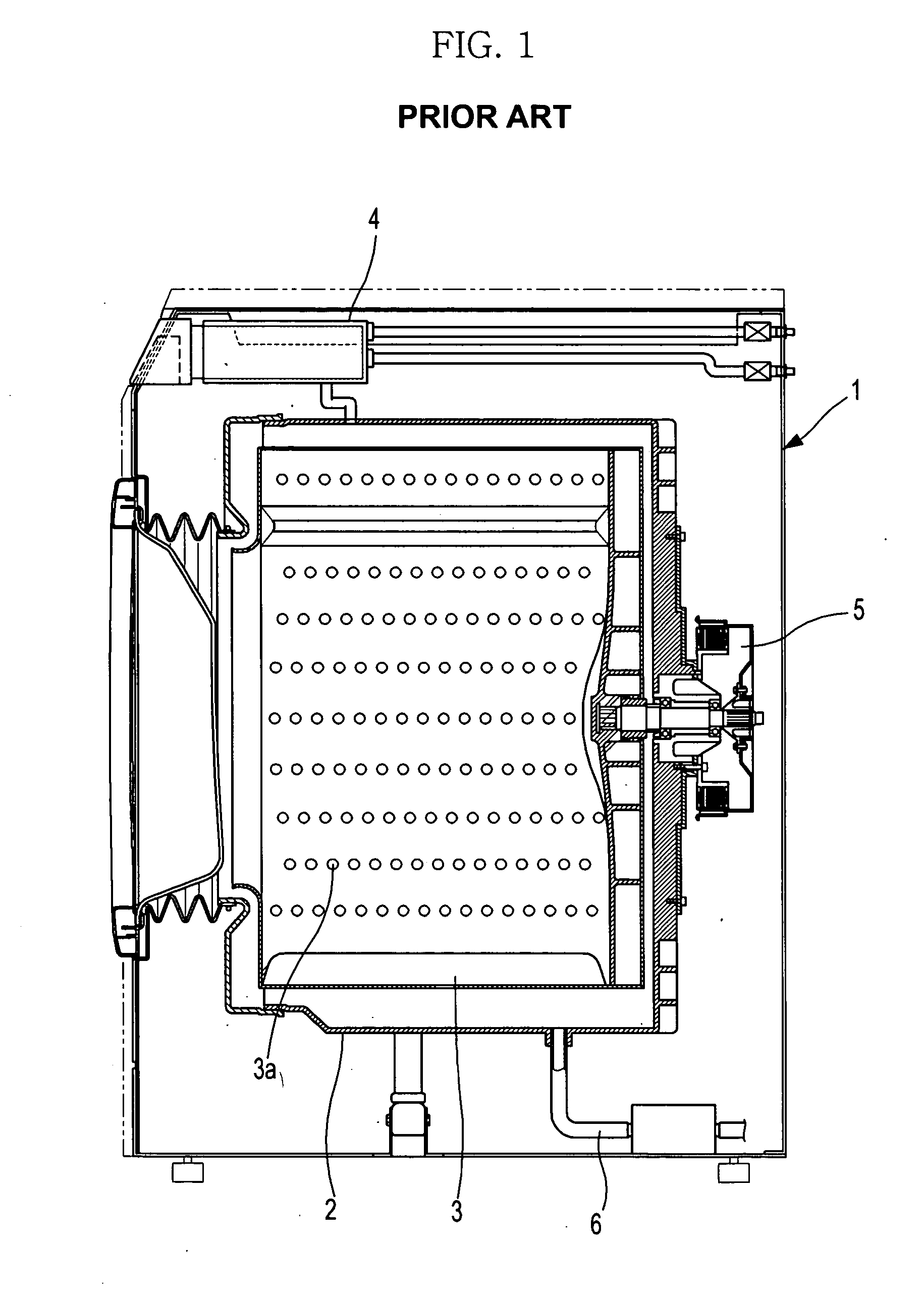
Since the washing water, which is stored in the tub 2 installed outside the drum 3, flows into the drum 3 and is supplied to the drum 3, the above conventional drum washing machine is disadvantageous in that washing water of an amount larger than the substantially necessary amount for washing laundry is consumed.
Since the drainage hole is opened even in the washing operation, the above drum washing-machine is disadvantageous in that the washing water in the drum is undulated by the movement of laundry and discharged to the outside of the drum through the drainage hole in the washing operation.
Then, the appropriate amount of the washing water in the drum cannot be maintained, and the washed state of the laundry is poor.
Further, since the drainage hole is formed through the upper portion of the drum of the above conventional drum washing machine and most of the washing water is located in the lower portion of the drum, the discharging efficiency of the washing water in the dehydrating operation is reduced.

Method used


Image

  • Drum washing machine
  • Drum washing machine
  • Drum washing machine

Examples


Embodiment Construction

[0033] Reference will now be made in detail to the embodiments of the present invention, examples of which are illustrated in the accompanying drawings, wherein like reference numerals refer to the like elements throughout. The embodiments are described below to explain the present invention by referring to the figures.

[0034] Reference will now be made in detail to the embodiment of the present invention, an example of which is illustrated in the accompanying drawings, wherein like reference numerals refer to like elements throughout. The embodiment is described below to explain the present invention by referring to the figures.

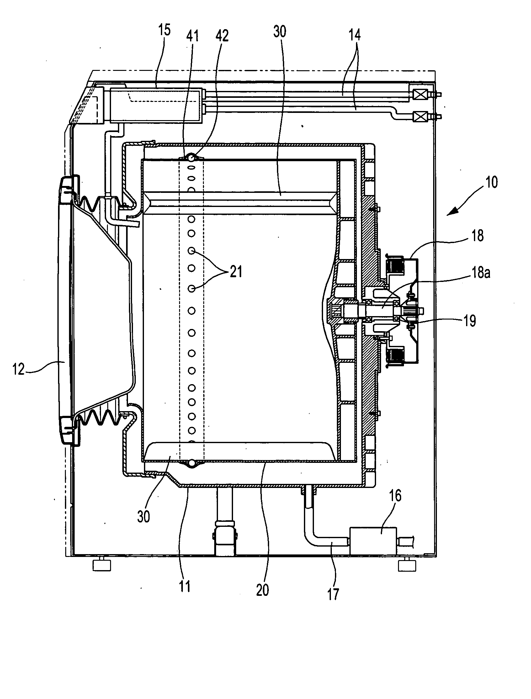
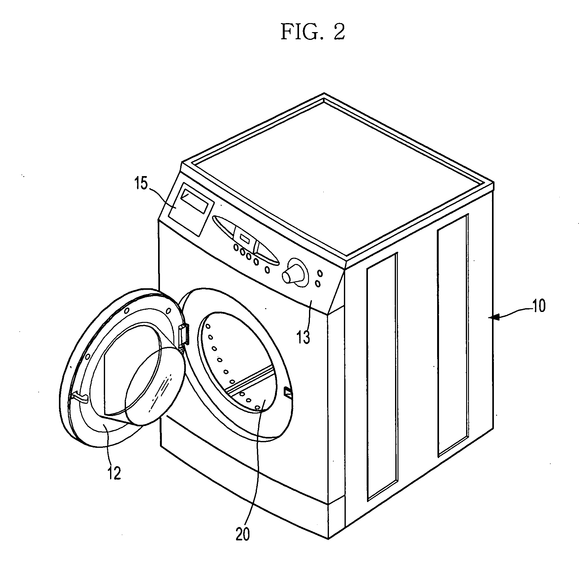
[0035]FIG. 2 illustrates a perspective view of a drum washing machine in accordance with an embodiment of the present invention, and FIG. 3 illustrates a sectional view of the drum washing machine shown in FIG. 2.

[0036] As shown in FIGS. 2 and 3, the drum washing machine of the present invention comprises a housing 10 forming the external appearance of the...


PUM


Abstract

A drum washing machine in which washing water is supplied directly to a drum to reduce consumption of the washing water, and is easily discharged from the drum in a dehydrating mode without leakage of the washing water from the drum in a washing mode. The drum washing machine includes an opening and closing device to open the dehydration holes by a centrifugal force only when the drum is rotated more than a designated speed. The opening and closing device includes opening and closing members to open and close the dehydration holes, and an elastic member to enable the opening and closing members to open and close the dehydration holes according to an intensity of the centrifugal force generated due to a rotation of the drum. The drum washing machine supplies the washing water directly to the drum, thereby preventing problems regarding the leakage or discharge of the washing water.

Description

CROSS-REFERENCE TO RELATED APPLICATIONS [0001] This application claims the benefit of Korean Patent Application No.10-2005-0072297, filed Aug. 8, 2005, in the Korean Intellectual Property Office, the disclosure of which is incorporated herein by reference. BACKGROUND OF THE INVENTION [0002] 1. Field of the Invention [0003] The present invention relates to a drum washing machine. More particularly, to a drum washing machine in which washing water is supplied directly to a drum therein so as to reduce consumption of the washing water, and is easily discharged from the drum in a dehydrating mode without the leakage of the washing water from the drum in a washing mode. [0004] 2. Description of the Related Art [0005] Washing machines are apparatuses for washing laundry using electricity, and are generally divided into vertical shaft washing machines, in which a rotary tub is vertically installed in a main body, and drum washing machines, in which a rotary tub is horizontally installed in...

Claims


Application Information

Patent Timeline
Patent Type & Authority Applications(United States)
IPC IPC(8): D06F35/00D06F25/00
CPCD06F37/04D06F39/08Y02B40/00
Inventor CHOI, DONG HYUNHUR, WOON GULEE, SE HYEONGCHOI, WON SEOK
Owner SAMSUNG ELECTRONICS CO LTD
Learn More