
Airborne particle removal system

Inactive Publication Date: 2007-02-08
MURPHY BRYAN W
View PDF3 Cites 26 Cited by
  • Summary
  • Abstract
  • Description
  • Claims
  • Application Information

AI Technical Summary

Benefits of technology

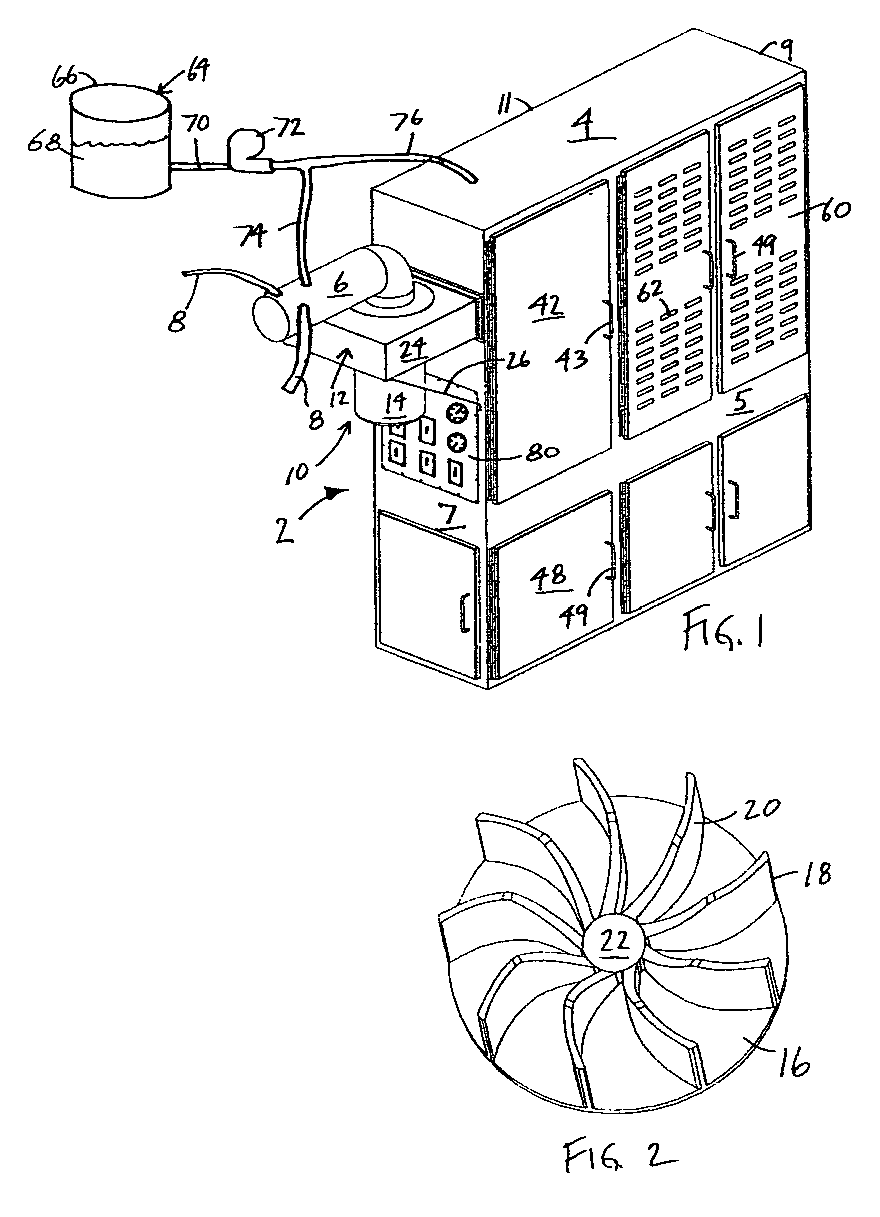
[0009] Airborne particle removal systems in accordance with the present invention are configured to remove particles that may or may not contain hazardous or infectious material. Such systems may advantageously operate while the industrial equipment is in operation, as well as provide a continuous means for machine cleaning and maintenance and work area cleaning and maintenance. Once the airborne particles and other waste materials have been removed from the machinery or work area, preferred embodiments of the present invention provide for a decontamination process to be initiated, either as a standard practice or as a preventive or corrective action where suspected contamination exists, using a liquid distribution system.
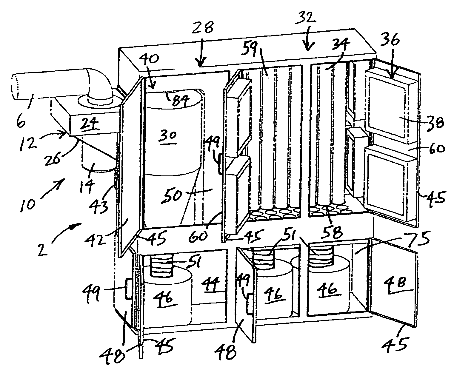
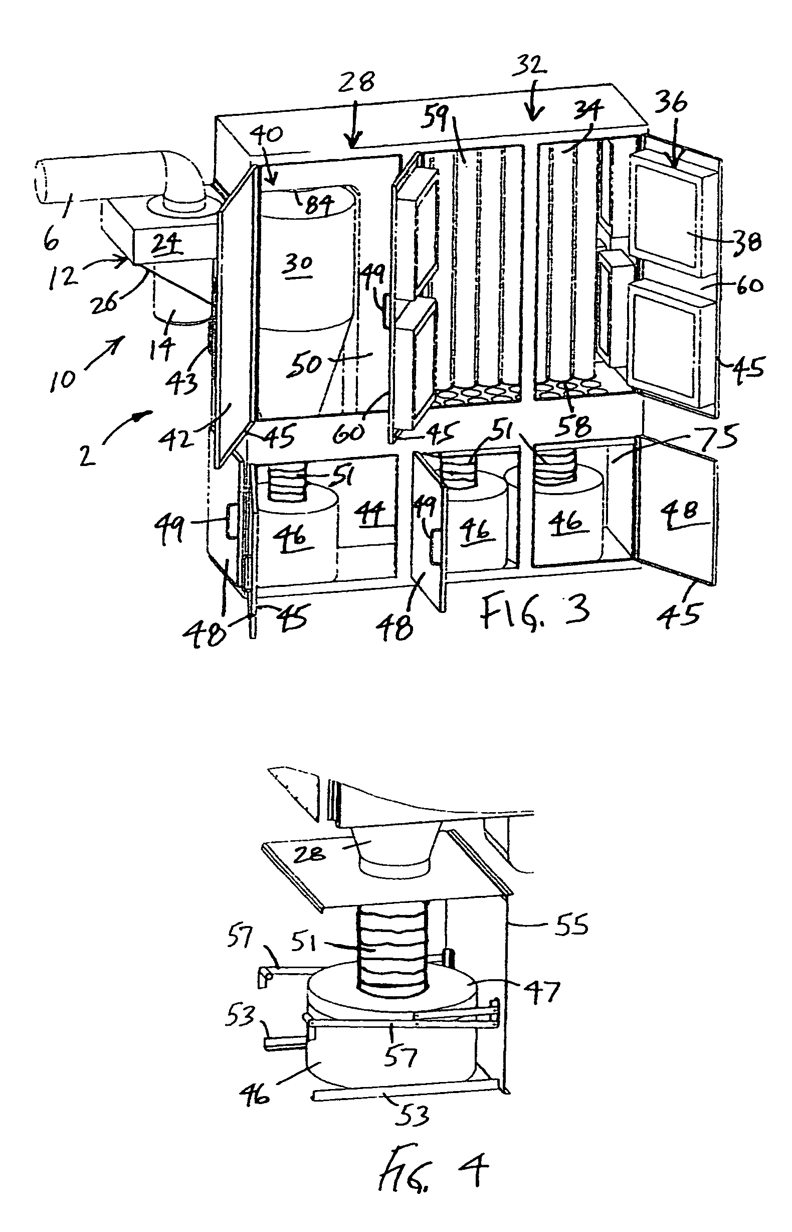
[0010] In accordance with one aspect, an airborne particle removal system includes a housing, and a vacuum assembly to introduce a flow of air into the housing. A cyclone dust collector is positioned in the housing downstream of the vacuum assembly with respect to the flow of air through the housing. A plurality of filter bags is positioned in the housing downstream of the cyclone dust collector with respect to the flow of air through the housing. A plurality of high efficiency particulate air filters is positioned in the housing downstream of the filter bags with respect to the flow of air through the housing. Thus the housing itself becomes an integral part of the filter system. Therefore, the apparatus for airborne particle removal comprises a unique airtight housing having a first filtering zone, a second filtering zone, and a third filtering zone, more efficiently moving air through the filtering system. This housing can also be waterproof.
[0013] Substantial advantage is achieved by providing an airborne particle removal system. In particular, such airborne particle removal systems allow for industrial equipment to be continuously cleaned while operating without extensive labor costs. This cleaning will allow the equipment to function more efficiently and remove airborne toxic by-products. Furthermore, containment of potentially hazardous particles greatly reduces any risks to equipment operators and maintenance personnel assigned to operate and maintain the equipment. In particular, because the filter is operating continuously during industrial operations, the level of hazardous particles can be maintained at very low levels at all times. This eliminates a buildup of dangerous levels of hazardous particles, toxic by-products or microbes in the air prior to stopping work and commencing conventional filtering operations.

Problems solved by technology

As products are made or packages travel through these systems, particles are generated that can prevent the equipment from remaining in good working order, and may also be potentially hazardous to operators.
In particular, certain elements within the machinery, such as imaging systems, bar code readers and optical character recognition systems, are adversely affected by the accumulation of particles.
This problem is compounded when large volumes of material are processed by such equipment, causing rapid accumulation of particles.
Further, the presence of hazardous particles, such as by-products like arsenic or asbestos, in the ambient environment presents a serious health and safety concern, especially given the potential for hazardous particles, toxins, or microbes being introduced by sabotage or terrorist activity.
Unfortunately, in many cases, the recommended preventive maintenance may be delayed because of the frequency and extensive down time required.
Such down time is extremely undesirable for many reasons, including the labor costs incurred in breaking down and cleaning the equipment and slowing or stopping of production schedules.
This system is limiting in that it does not provide continuous cleaning, nor can it provide for the removal of hazardous or infectious material.
The system of Thomas is limiting in that it is only effective for dust particles and cannot process larger types of waste or potentially hazardous or infectious materials.
Minakawa is limiting in that it does not provide for the removal of hazardous or infectious material.

Method used


Image

  • Airborne particle removal system
  • Airborne particle removal system
  • Airborne particle removal system

Examples


Embodiment Construction

[0023] Airborne particle removal systems in accordance with the present invention can provide a cleaning system for removing dust and particles from various types of industrial equipment, and provide a means for decontamination in the event that biologically hazardous materials are present in the collected material. The term “particles” is meant to include not only inanimate matter such as metal ions, insecticides, herbicides, toxic chemical elements and compounds, radioactive contaminants, and the like, but also spores, microbes, viruses, and other hazardous biological material.

[0024] Particular embodiments of the airborne particle removal system are particularly adaptable to equipment having a variety of different processing stations through which product or material is manufactured and / or transported, usually by a conveyer system or equivalent. The airborne particle removal system will preferably be operational at the same time that product or material is processed or directed t...


PUM

PropertyMeasurementUnit
Lengthaaaaaaaaaa
Lengthaaaaaaaaaa
Flow rateaaaaaaaaaa

Abstract

An airborne particle removal system includes a vacuum assembly to introduce a flow of air into a housing. A cyclone dust collector is positioned in the housing downstream of the vacuum assembly with respect to the flow of air through the housing. A plurality of filter bags is positioned in the housing downstream of the cyclone dust collector with respect to the flow of air through the housing. A plurality of high efficiency particulate air filters is positioned in the housing downstream of the filter bags with respect to the flow of air through the housing. In certain preferred embodiments, a liquid distribution system introduces a liquid agent into the system.

Description

RELATED APPLICATION(S) [0001] This application is a Continuation-in-Part and claims priority to U.S. patent application Ser. No. 10 / 314,919, filed Dec. 9, 2002, which claims the benefit of U.S. Provisional Application No. 60 / 338,293, filed Dec. 7, 2001, the entire teachings of both which are incorporated herein by reference.FIELD OF THE INVENTION [0002] The present invention relates to a system for removing airborne particles and, more particularly, to a system that can remove such particles from various types of industrial equipment while the equipment is operating. BACKGROUND OF THE INVENTION [0003] Machinery such as industrial packing equipment, pharmaceutical packaging systems, modern mail processing equipment, wood and plastic processing equipment, fiberglass processing equipment, boat building equipment, and other types of machinery can generate and be affected by airborne particulates or particles. Such airborne particles may be present inside or outside of the machinery, and...

Claims


Application Information

Patent Timeline
IPC IPC(8): B01D50/00B01D45/16B01D46/02B01D47/06
CPCB01D45/16B01D46/02B01D47/06B01D2279/51B01D2267/40B01D2275/10B01D50/002B01D50/20
Inventor MURPHY, BRYAN W.
Owner MURPHY BRYAN W
Learn More