
Large plush towel warmer and dehumidifier

a dehumidifier and plush technology, applied in the field of bathroom towel warmers, can solve the problems of irritating user noise levels, and achieve the effect of rapid respons

Inactive Publication Date: 2007-02-08
HUNTS BARNEY DEAN
View PDF12 Cites 31 Cited by
  • Summary
  • Abstract
  • Description
  • Claims
  • Application Information

AI Technical Summary

Benefits of technology

The present invention is a towel warmer that is designed to quickly and safely heat a large plush towel without damaging it. It uses a multiplicity of lower rpm, quiet blowers that work together to produce the necessary pressure to assure adequate air flow. The towel is enclosed in a substantially airtight configuration and re-circulates the hot air, regardless of its condition. The invention also includes a dehumidifying embodiment that periodically actuates internal baffles to allow fresh air to displace moisture-laden air and reduce the moisture content in the towel. The overall control cycle is designed to minimize the periods during which air flows through the unit, ensuring efficient use of the towel warmer.

Problems solved by technology

Currently available quiet, low cost blowers that are adequate when only a few layers of towel are involved do not sustain a sufficient pressure gradient to penetrate the depth of towel anticipated in this invention and substitution of higher rpm blowers creates unacceptable noise levels that are irritating to the user.

Method used


Image

  • Large plush towel warmer and dehumidifier
  • Large plush towel warmer and dehumidifier
  • Large plush towel warmer and dehumidifier

Examples


Embodiment Construction

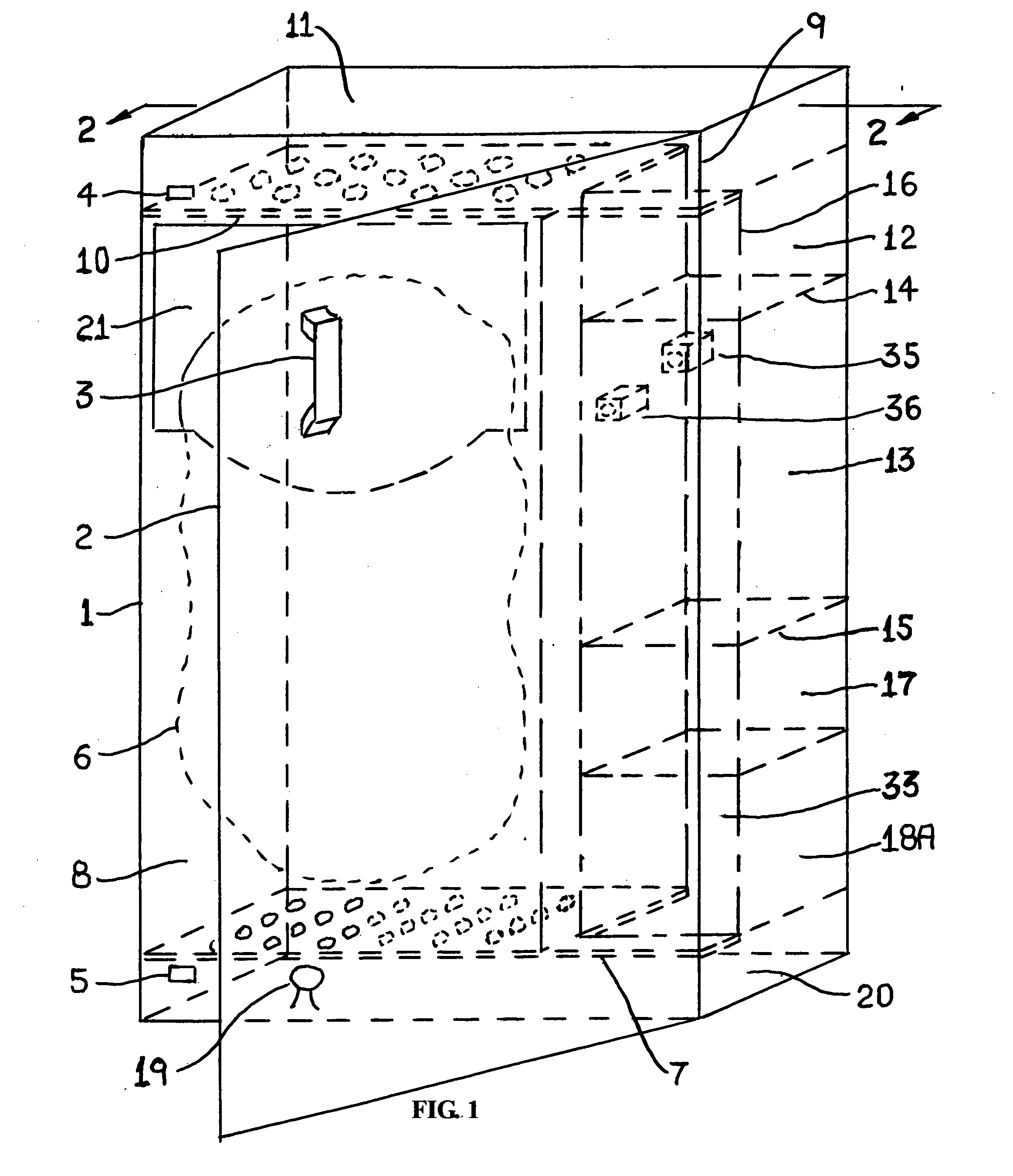
[0017] Referring to FIGS. 1 and 2, the present invention includes a substantially airtight enclosure 1 having a sealable access means in the form of a door 2 which is moveable into a closed position by handle 3 and held in a closed position by a magnet or similar catches 4 and 5. Door 2 enables placing a towel 6 to be warmed in the enclosure 1 and to enable removing the warm towel 6 from enclosure 1. As illustrated in FIG. 1, the towel 6 is in a rumpled condition, but it could just as well be in a neatly folded condition, since regardless of the condition of the towel 6, it is completely warmed throughout its bulk by means of total immersion in the temperature controlled forced hot air being circulated within enclosure 1.

[0018] A first means in the form of a shelf 7 to support the towel 6 and having perforated air passages there through is disposed within the air tight enclosure 1. The cavity 8 in which the towel is heated is defined by the access means door 2, first means shelf 7,...


PUM

PropertyMeasurementUnit
temperatureaaaaaaaaaa
electrical poweraaaaaaaaaa
pressureaaaaaaaaaa

Abstract

An increased air pressure forced hot air towel warmer comprising a substantially airtight enclosure configured to be more desirable and user friendly when placed in close proximity to a tub or shower whether mounted within cabinetry, on the wall or when permanently installed between existing standard 16 inch on center wall support studs while protruding as little as possible into the room. Intended for use with large area plush towels and bath sheets for which insertion in a limited width wall enclosure or shallow depth cabinetry leads to greater vertical depth of towel material to be penetrated and substantially increases the resistance to air flow, therefore back pressure, thereby necessitating increased supply pressure to maintain adequate hot air flow through the towel. Increased supply pressure is created without objectionable noise by use of low noise rotary blowers and associated pressure accumulator cavities arranged in tandem such that their respective pressure gradients are additive. Experience has also shown that all towels exhibit some degree of adsorbed moisture, the present invention includes an embodiment for increasing user satisfaction by removing excess adsorbed moisture during the warming cycle to achieve dehumidification by means of periodic short time interval ejection of the warmed moisture laden air within the enclosure with simultaneous replacement by room air to sequentially reduce the moisture content retained within the warmed towel.

Description

BACKGROUND OF THE INVENTION [0001] The present invention relates to bathroom towel warmers and more particularly to improved hot air towel warmer configurations intended for use with large area plush bath towels and bath sheets whose size and material volume increase the difficulty of achieving sufficient air passage through the towel to assure heating adequately within the time of a typical bath or shower. [0002] It is Applicants desire to provide in a bath or shower area a compact, esthetically attractive device capable of achieving rapid, uniform heating of articles such as clothing or towels and the like as a preliminary to use. A primary objective of the present invention is to assure adequate air flow through increased depth towel fabric by using readily available low cost blowers oriented in tandem. It is a further objective of the present invention to provide a physical embodiment including a means for removing excess adsorbed moisture during the warming cycle to achieve deh...

Claims


Application Information

Patent Timeline
Patent Type & Authority Applications(United States)
IPC IPC(8): F26B19/00F26B25/06D06F34/26
CPCD06F58/10D06F34/26
Inventor HUNTS, BARNEY
Owner HUNTS BARNEY DEAN
Learn More