Cross joint
a cross-joint and needle bearing technology, applied in the direction of engine components, mechanical devices, couplings, etc., can solve the problems of noise emission, rise in manufacturing costs, and difficulty in bringing the spherical protrusion provided on the inner surface of the cup of the needle bearing into contact with the conical hole of the spider shaft with a proper pre-load, so as to avoid noise emission, smooth steering feeling, and reduce manufacturing costs
- Summary
- Abstract
- Description
- Claims
- Application Information
AI Technical Summary
Benefits of technology
Problems solved by technology
Method used
Image
Examples
first embodiment
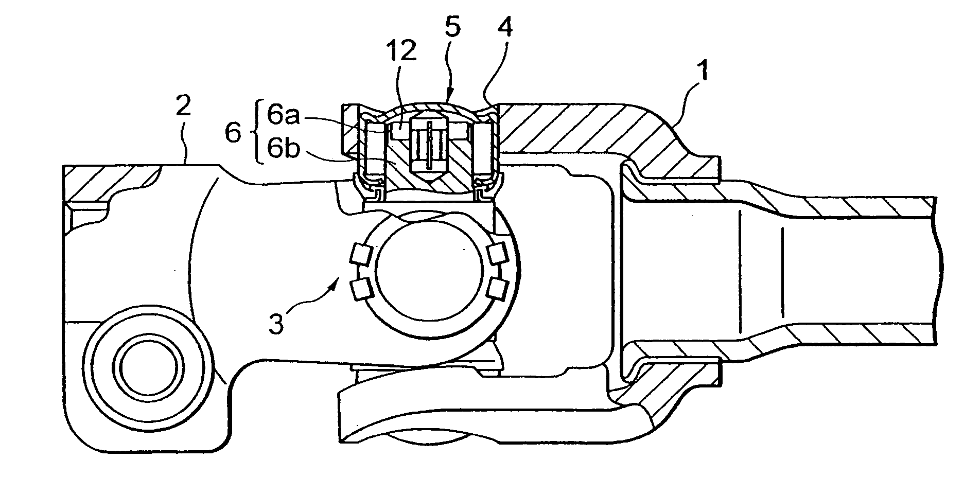
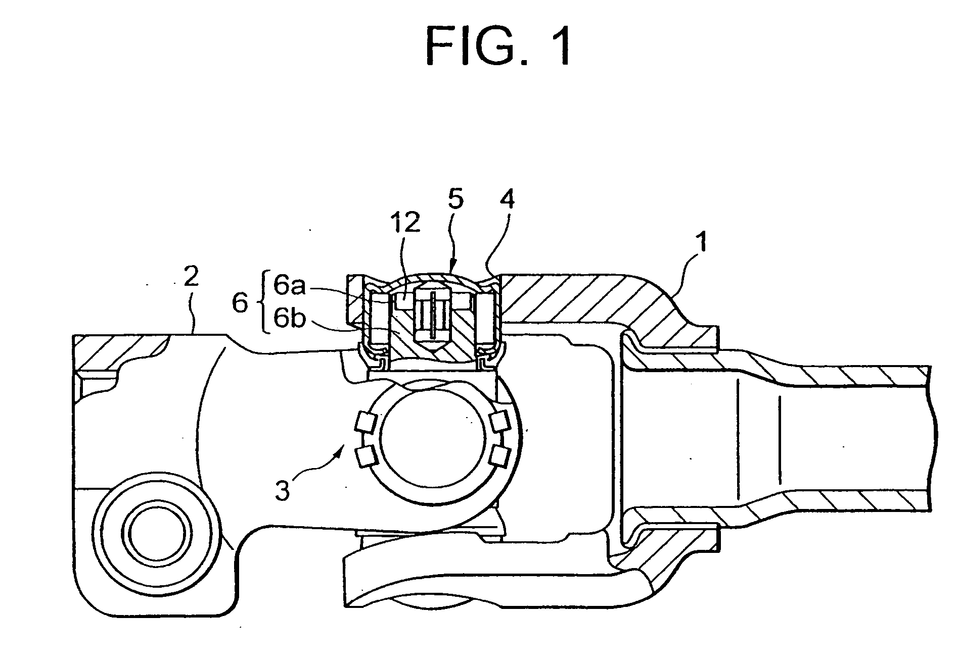
[0038]FIG. 1 is a side view including a partially cut-off section, showing a cross joint in a first embodiment of the present invention. FIG. 2 is a sectional view of the cross joint illustrated in FIG. 1.
[0039] As shown in FIG. 1, the cross joint has a cross-shaped spider 3 interposed between a pair of yokes 1 and 2. To be more specific, as shown in FIG. 2, a spider shaft 6 is rotatably fitted into a bearing hole 4 of the yoke 1 through a needle bearing 5. A seal member 7 is provided along an outer periphery of a lower portion of the spider shaft 6. The yoke may be manufactured by any one of sheet metal working, forging and casting and composed of any one of ferro-series and alumi-series materials.
[0040] Further, a pin 9 composed of a synthetic resin is inserted into an axial hole 8 formed in an axial core of the spider shaft 6. The needle bearing 5 is provided with a metallic cup 10 fitted in the bearing hole 4. A plurality of rolling members (rollers) 11 are arranged inwardly o...
second embodiment
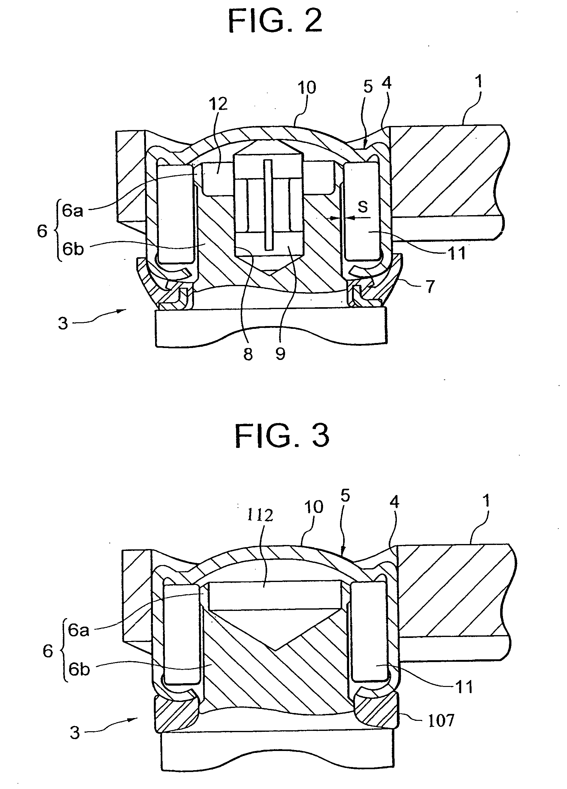
[0048]FIG. 3 is a sectional view showing a cross joint in a second embodiment of the present invention. according to the second embodiment, the synthetic resin pin 9 is not provided, and therefore the bottomed hole 112 takes a conical shape, which leads to a less cost than in the first embodiment.
[0049] The cross joint in the second embodiment is, however, limited to the use in the driving room. Further, the seal member 107 is composed of a nitrile rubber. Other configurations and operations are the same as those in the first embodiment.
third embodiment
[0050]FIG. 4 is a sectional view showing a cross joint in a third embodiment of the present invention. According to the third embodiment, the contact portion of the spider shaft is formed as a separate member. Namely, the spider shaft 206 is formed with an axial hole 13, and a separate spacer 14 is fitted into this axial hole 13.
[0051] A protrusion 14a of this spacer 14 is press-fitted into the axial hole 13, and a thin ring-shaped portion 14b of the spacer 14 functions as the contact portion 6a in the first and second embodiments does. According to the third embodiment, the grinding of the outside diametric portion of the spider is easier than in the first and second embodiments. Other configurations and operations are the same as those in the first embodiment.
PUM
 Abstract
Description
Claims
Application Information
 - R&D
- Intellectual Property
- Life Sciences
- Materials
- Tech Scout
- Unparalleled Data Quality
- Higher Quality Content
- 60% Fewer Hallucinations
Browse by: Latest US Patents, China's latest patents, Technical Efficacy Thesaurus, Application Domain, Technology Topic, Popular Technical Reports.
© 2025 PatSnap. All rights reserved.Legal|Privacy policy|Modern Slavery Act Transparency Statement|Sitemap|About US| Contact US: help@patsnap.com


