Eureka AIR delivers breakthrough ideas for toughest innovation challenges, trusted by R&D personnel around the world.

Method and device for gathering sheets

a technology of printed sheets and methods, applied in the direction of article feeders, article delivery, article separation, etc., can solve the problems of decollating devices, corresponding frictional forces, and markings on sensitive surfaces, and achieve the effects of simple pressure control of air cushions, low friction, and high withdrawal transport speed

Inactive Publication Date: 2007-02-01
KOLBUS
View PDF3 Cites 1 Cited by
  • Summary
  • Abstract
  • Description
  • Claims
  • Application Information

AI Technical Summary

Benefits of technology

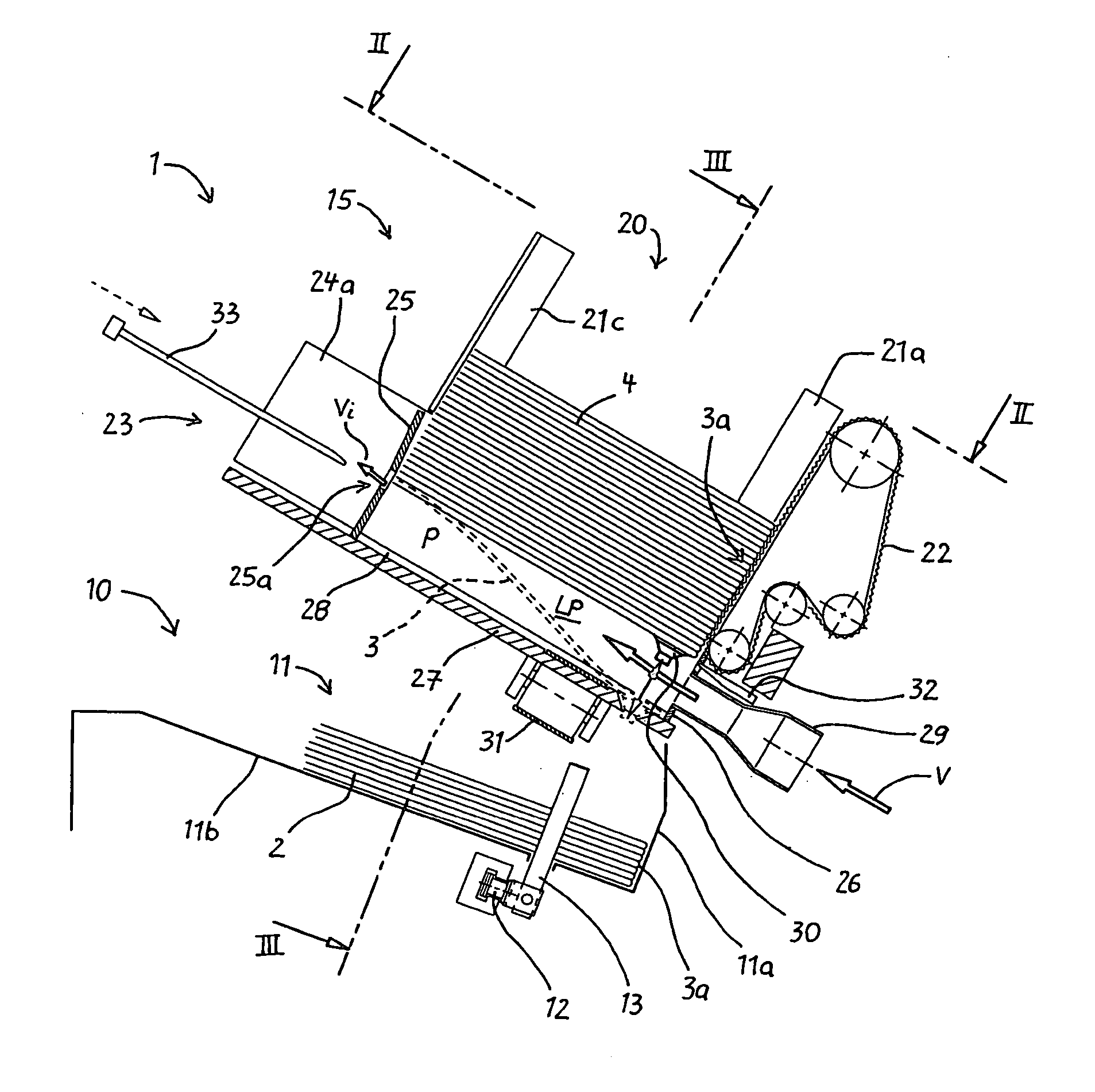
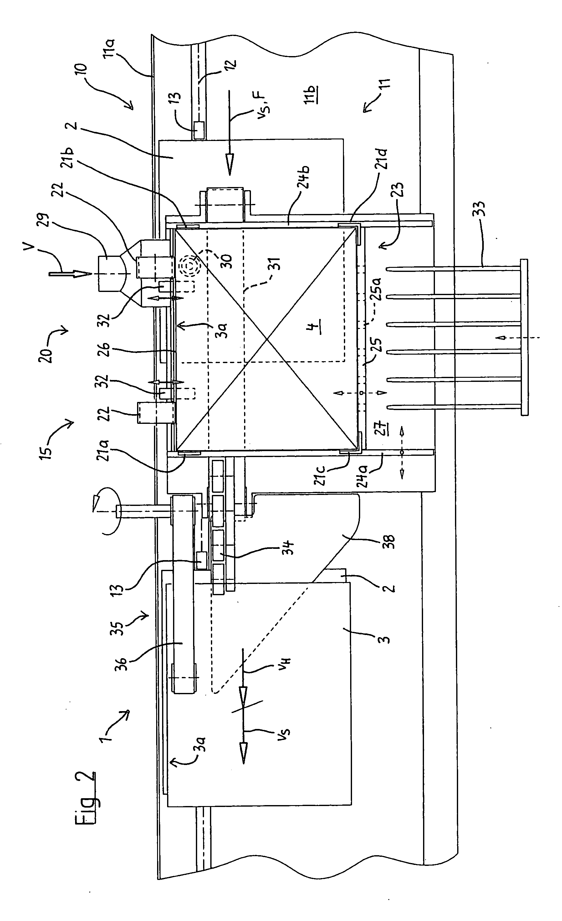
"The present invention is about a method and device for gathering printed sheets, particularly signatures and individual sheets, and achieving a reliable and careful decollation of the sheets. The invention uses an air cushion to support the sheet stack, which prevents the cushion from collapsing when the bottom sheet is lifted off. The air cushion is produced by a blast air current that is introduced laterally underneath the stack. The sheet that is completely separated from the stack is pressed onto a supporting surface in the form of a transport means by the pressure of the air cushion. The invention also maintains a certain height of the stack underside by ventilating the air cushion. The sheets are transported away parallel to the transport direction of the collecting conveyor and delivered to the collecting conveyor with an essentially synchronous transport speed. The sheets decollated from the magazine are delivered to the collecting conveyor without a change of direction."

Problems solved by technology

One disadvantage of known decollating devices can be seen in that the weight of the signature stack rests on the respective bottom signature such that corresponding frictional forces are generated between the bottom signature to be withdrawn and the following signature of the stack.
This can result in markings on sensitive surfaces.
However, this is frequently only possible regionally because the introduced blast air escapes from the stack in accordance with the principle of least resistance.

Method used


Image

  • Method and device for gathering sheets
  • Method and device for gathering sheets
  • Method and device for gathering sheets

Examples


Embodiment Construction

[0015] The figures show a gathering machine that is identified as a whole by the reference symbol 1, comprising a collecting conveyor 10 and several feeder stations 15 that are arranged in a row above the collecting conveyor, wherein only a single feeder station is illustrated in the figures. In each of these feeder stations 15, a single signature 3 is respectively withdrawn from a source stack 4 of identical signatures and delivered to the collecting conveyor 10 in order to form collated stacks. The collecting conveyor 10 is formed by a transport channel 11 with an inclined channel bottom 11b and a channel wall 11a that extends perpendicular thereto, as well as a transport chain 12 that is driven in the (collecting) transport direction F with a continuous transport speed vS and includes pushers 13 that are uniformly spaced apart from one another and advance the book blocks 2 being formed in the transport channel 11, wherein the spine 3a of the book block or the signature 3 adjoins ...


PUM

PropertyMeasurementUnit
blast air currentaaaaaaaaaa
pressureaaaaaaaaaa
elevationaaaaaaaaaa

Abstract

During the gathering process, an individual signature is respectively withdrawn from several collections of identical signatures, wherein the various decollated signatures are delivered to a collecting conveyor in order to form stacks. In this case, the sheets need to be reliably and carefully decollated. The invention proposes that the sheets (3) of a collection are made available in the form of a stack (4), wherein the stack (4) is essentially supported by an air cushion (LP), that the bottom sheet (3) is at least regionally lifted off the stack (4) with the aid of a separating tool (30), that the air cushion (LP) is produced between the bottom sheet (3) and the residual stack (4), and that the sheet (3) is delivered to the collecting conveyor (10). The lifted-off sheet is completely separated from the stack by the air cushion such that the sheet can be transported out of the magazine with absolutely no friction relative to the stack 4 situated above the separated sheet.

Description

BACKGROUND OF THE INVENTION [0001] The invention pertains to a method and a device for gathering printed sheets, particularly signatures and / or individual sheets. [0002] During the gathering process in a book binding system, an individual signature is respectively withdrawn from several collections of identical signatures, wherein the various decollated signatures are delivered to a collecting conveyor in order to form stacks. [0003] Known gathering machines feature feeder stations that are arranged in a row and respectively consist of a magazine for accommodating a signature stack, a withdrawal drum with a gripper mechanism for taking hold of and withdrawing the respective bottom signature that is tilted away from the signature stack, and an intermediate support for temporarily depositing the decollated signature. The collecting conveyor features a collecting channel that is oriented perpendicular to the signature withdrawal direction, wherein pushers of a transport chain moving in...

Claims


Application Information

Patent Timeline
Patent Type & Authority Applications(United States)
IPC IPC(8): B65H29/32
CPCB65H1/06B65H3/085B65H3/48B65H39/043B65H39/055B65H2301/4352B65H2301/4473B65H2406/11B65H2301/4478B65H2220/02B65H2220/01
Inventor WALTHER, ANDREAS
Owner KOLBUS
Why Eureka
Eureka Blog
Learn More