
Invert measuring device

a measuring device and inverter technology, applied in the direction of mechanical diameter measurement, measurement gauge, instruments, etc., can solve the problems of time-consuming, dangerous, cumbersome,

Inactive Publication Date: 2007-02-01
WILKINSON & ASSOCS
View PDF7 Cites 12 Cited by
  • Summary
  • Abstract
  • Description
  • Claims
  • Application Information

AI Technical Summary

Benefits of technology

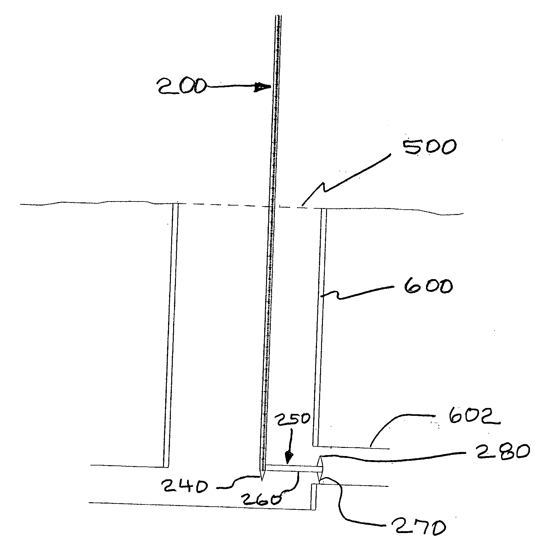
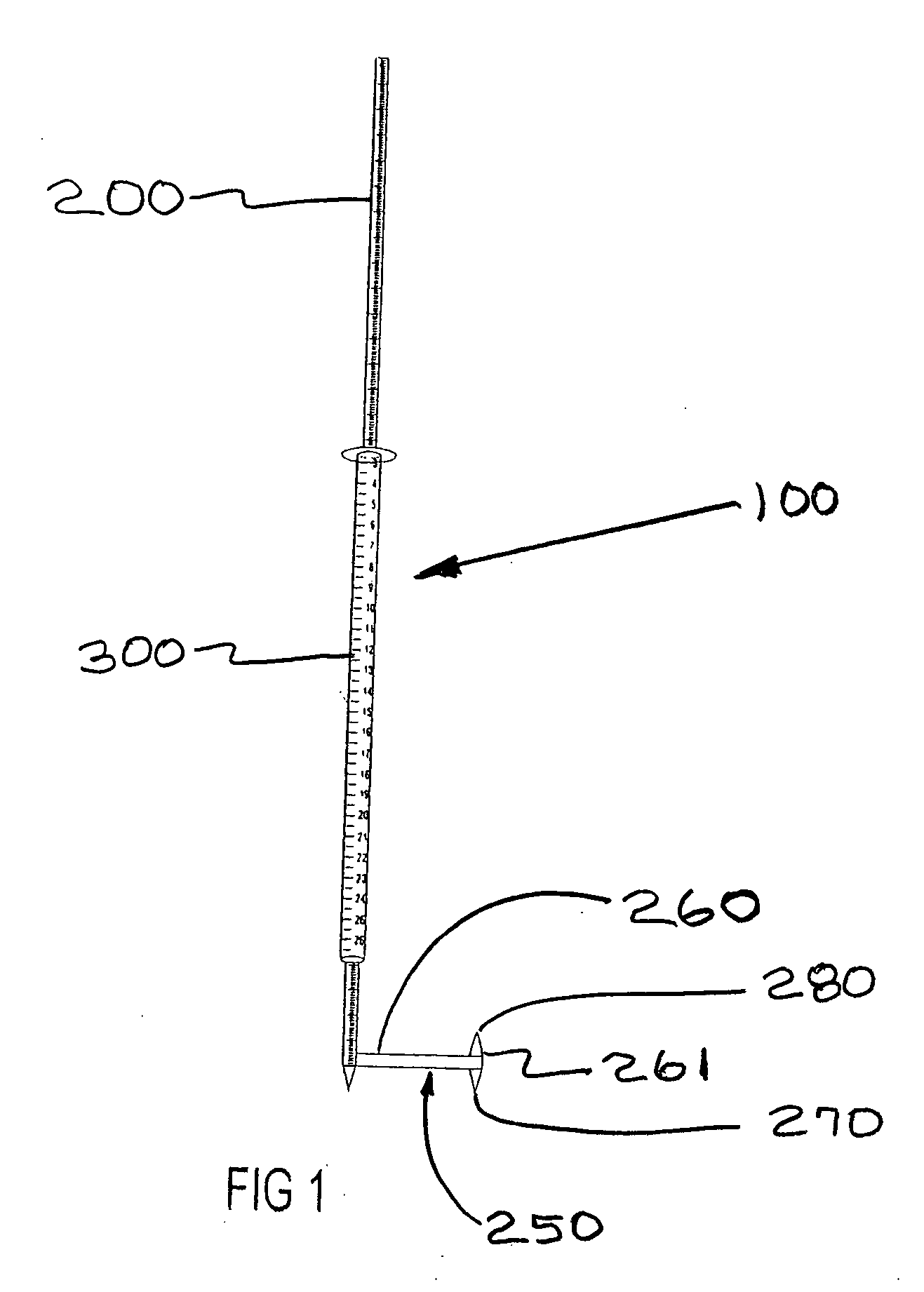
The invention provides a measuring device for surveying professionals that includes an invert measuring rod, a foot assembly, and a diameter measuring sleeve. The device can be used to obtain inlet invert and pipe diameter measurements. The measuring rod has a plurality of rod segments that can be joined together to form a continuous rod, and the diameter measuring sleeve can be slid along the rod to a desired position. The device also includes a measuring scale with gradations and numbers for easy reading. The foot assembly has a guide rod and conical feet for easy connection to the invert measuring rod. The measuring device can be used to obtain the inlet invert measurement by passing through an inlet entrance and lowering the measuring device through the inlet until the conical rod tip touches the bottom of the inlet. The device can also be used to obtain the pipe diameter measurement by passing through an inlet and lowering the measuring device through the pipe until the conical foot passes into the pipe.

Problems solved by technology

However, physically entering an inlet, such as a public sewer that might be covered by a manhole cover, or other subsurface structure, can be time consuming, cumbersome, and dangerous.

Method used


Image

  • Invert measuring device
  • Invert measuring device
  • Invert measuring device

Examples


Embodiment Construction

[0025] Referring to FIG. 1, a preferred embodiment of the measuring device is shown and designated generally 100. Measuring device 100 preferably includes an invert measuring rod 200, a foot assembly 250, and a diameter measuring sleeve 300, each addressed below.

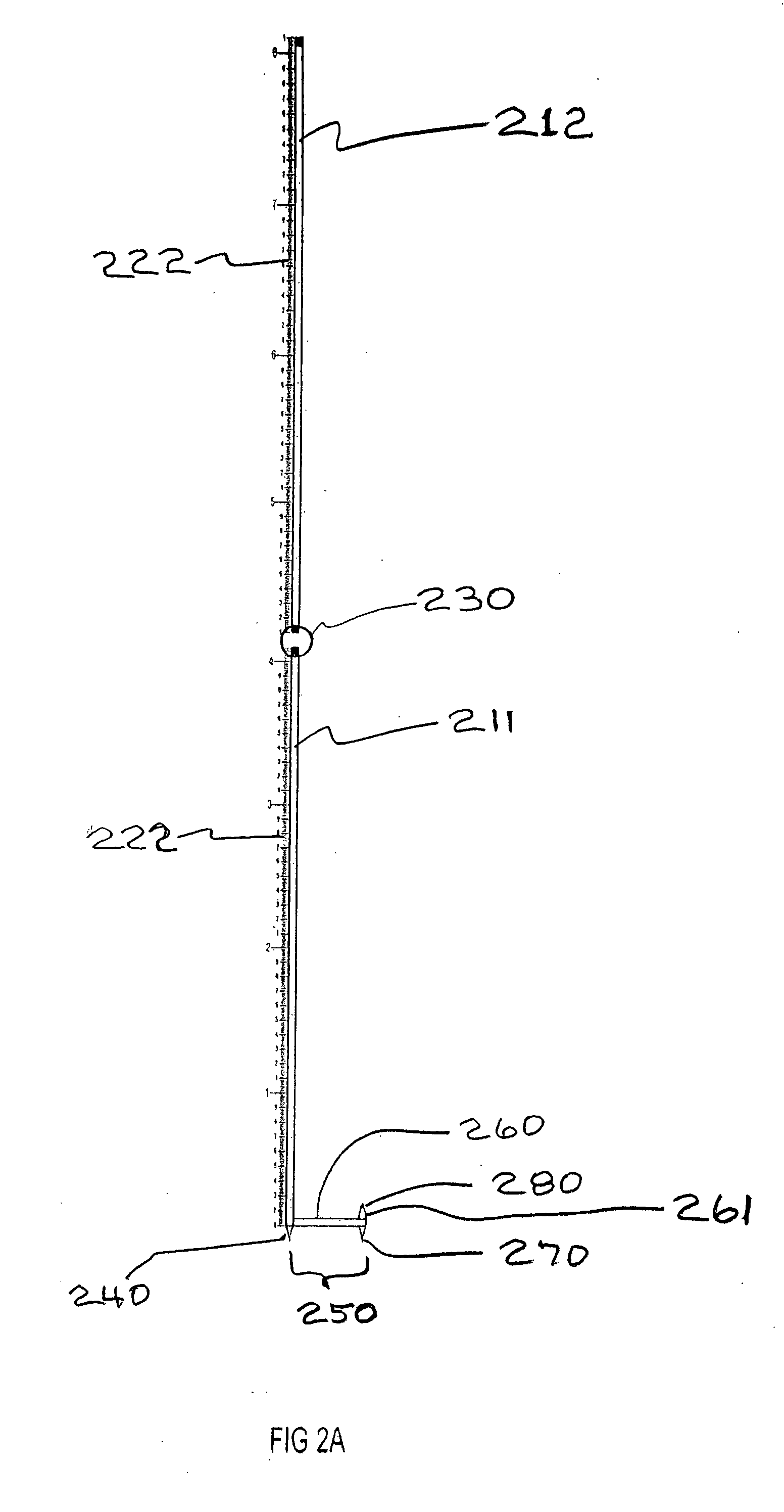
[0026] Referring to FIGS. 2a through 2c, invert measuring rod 200 preferably includes rod segments 211 and 212, shown in FIG. 2a, and rod segments 213, 214, and 215, shown in FIG. 2b. Each of rod segments 211, 212, 213, 214, and 215 preferably includes a threaded bore 231 at a first end and an externally threaded stud 232 at a second end. As shown in FIG. 2c, threaded bores 231 and studs 232 of adjacent rod segments threadedly engage one another to form joints 230 removably connecting adjacent rod segments 211, 212, 213, 214, and 215 to one another. Invert measuring rod 200 preferably includes a conical rod tip 240, illustrated in FIG. 2A, extending downwardly from rod segment 211. Rod tip 240 defines the lower end of inver...


PUM


Abstract

A measuring device for obtaining inlet invert measurements, pipe invert measurements, and pipe diameter measurements includes an invert measuring rod having a plurality of rod segments, each a threaded bore at a first end and an axially extending threaded stud at a second end, a foot assembly comprising a guide rod removably connected to and extending perpendicularly from the bottom of the lower segment of the continuous rod, when connected having a free end opposite the connecting with the invert measuring rod with a bottom conical foot connected to and extending downwardly from the free end of the guide rod and parallel to the invert measuring rod, the bottom conical foot having an axial length the same as axial length of the conical rod tip, and extending from the free end of the guide rod parallel to the invert measuring rod and a diameter measuring sleeve, having a tubular portion positionable concentrically about the invert measuring rod and having an inner diameter just greater than the outer diameter of the invert measuring rod to create a friction fit therebetween permitting sliding movement of the tubular portion along the length of the invert measuring rod to a selected position and retaining the tubular portion at the selected position on the rod with a measurement scale disposed lengthwise on the tubular portion with numerical indicators of measure increasing from the collar to the bottom of the tubular portion.

Description

CROSS REFERENCE TO RELATED PATENT APPLICATION [0001] This patent application claims the benefit under 35 USC 119 of the filing date of U.S. provisional application Ser. No. 60 / 651,185, filed 9 Feb. 2005 in the names of John Wilkinson, Ed Wilkinson and Richard Yandrick. The disclosure of provisional application Ser. No. 60 / 651,185 is hereby incorporated by reference.BACKGROUND OF THE INVENTION [0002] 1. Field of Invention [0003] The invention relates to a measuring device having an invert measuring rod and a diameter measuring sleeve, for obtaining inlet invert measurements, pipe invert measurements, and pipe diameter measurements. [0004] 2. Description of the Related Art [0005] Professionals in land surveying, municipal maintenance, and related industries often must obtain depth measurements of inlets, manholes, and other subsurface structures. Surveying professionals also often must obtain depth and diameter measurements of underground pipes leading to and from subterranean inlets ...

Claims


Application Information

Patent Timeline
Patent Type & Authority Applications(United States)
IPC IPC(8): G01B3/00
CPCG01B5/12G01B3/28
Inventor WILKINSON, JOHNWILKINSON, EDWARDYANDRICK, RICHARD
Owner WILKINSON & ASSOCS
Learn More