Eureka AIR delivers breakthrough ideas for toughest innovation challenges, trusted by R&D personnel around the world.

Intraluminal device with improved tapered beams

a technology of tapered beams and beams, applied in the field of medical devices, can solve the problems of fatigue failure and require more robust beam designs

Active Publication Date: 2007-01-25
COOK MEDICAL TECH LLC
View PDF6 Cites 14 Cited by
  • Summary
  • Abstract
  • Description
  • Claims
  • Application Information

AI Technical Summary

Benefits of technology

The invention is about a new design for a strut used in intraluminal devices. The strut has an end portion that is connected to a bend and a middle portion. The end portion has a first side surface and a second side surface. The width of the strut is proportional to the distance from the second end raised to a power between 0.6 and 0.4. This design helps to distribute the strain evenly along the length of the strut, which improves fatigue life and makes the device more efficient. The invention also includes a method for making the strut and an intraluminal device that includes the strut.

Problems solved by technology

This is undesirable because certain parts of the beam will experience higher strain levels, which may lead to fatigue failures or require more robust beam designs.

Method used


Image

  • Intraluminal device with improved tapered beams
  • Intraluminal device with improved tapered beams
  • Intraluminal device with improved tapered beams

Examples


Embodiment Construction

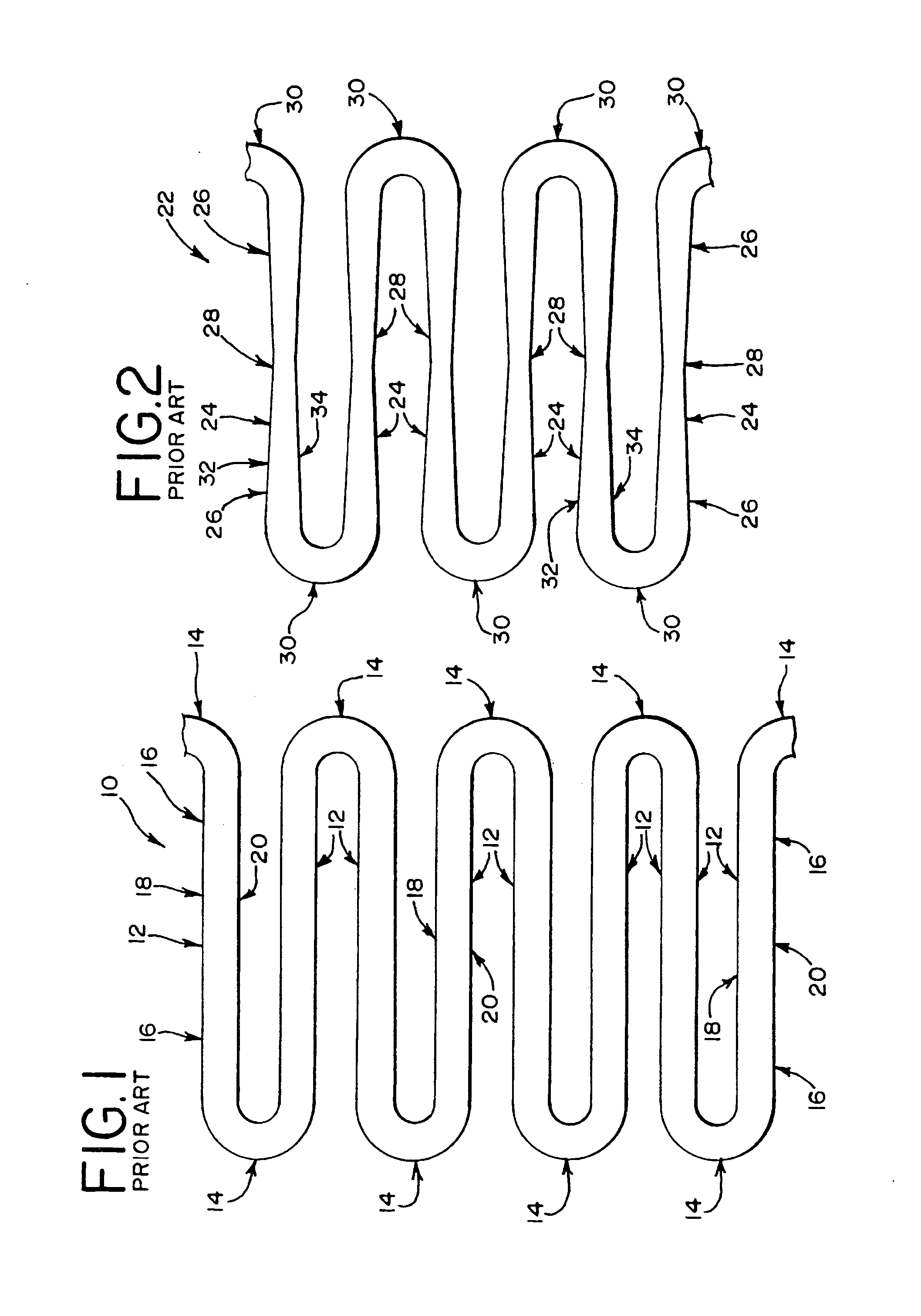
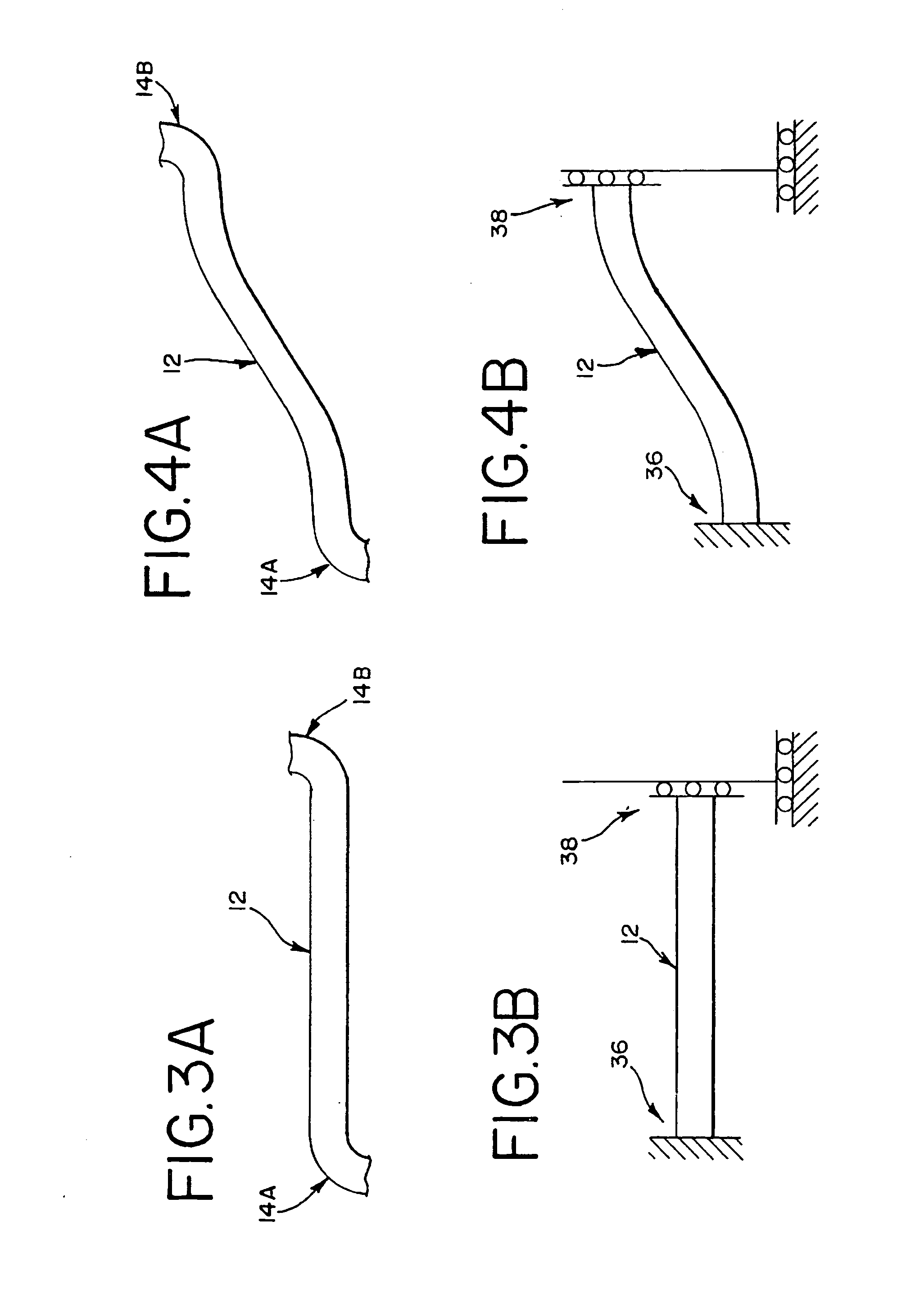
[0059] Referring now to the drawings, and particularly to FIG. 1, a prior art stent structure 10 is shown. As is well known in the art, a stent structure 10 typically includes a series of struts 12, or beams 12, interconnected by a series of bends 14. Many different types of materials may be used to form stent structures like the structure 10 shown in FIG. 1. For example, in the case of self-expandable stents, it is normally preferred to use an elastic material like nitinol or stainless steel. One common manufacturing technique for making a stent structure 10 is laser cutting the structure 10 from a metal cannula. However, other known methods may also be used. As shown in FIG. 1, a bend 14 is connected to each end portion 16 of the struts 12, and different struts 12 are connected to each side of the bends 14. The bends 14 on opposing ends of each strut 12 face in opposite directions. The bends 14 and struts 12 may also be further connected to other struts and bends or other structur...


PUM


Abstract

A strut, or beam, is provided for intraluminal devices. Strain which is introduced into a stent or other intraluminal device is distributed more evenly along the length of the improved strut by maintaining a substantially constant strain level along the length of an end portion. This may increase fatigue life or improve the performance of devices using the improved strut. The strain along the length of the end portion may be maintained substantially constant by varying a section property of the strut, including the width, thickness, cross-sectional area, material property or other characteristic of the end portion.

Description

RELATED APPLICATIONS [0001] This application claims priority to U.S. Provisional Application No. 60 / 690,776, filed Jun. 15, 2005, which is hereby incorporated by reference herein. [0002] This application is related to U.S. patent application Ser. No. ______ (Attorney Docket No. 8627-1243), incorporated herein by reference and entitled Intraluminal Device With Unsymmetric Tapered Beams, filed by the same inventors on the same day as the present application.BACKGROUND [0003] The present invention relates generally to medical devices and more particularly to intraluminal devices suitable for percutaneous transluminal delivery into a body. [0004] A variety of intraluminal devices are known to those in the medical arts, including stents, stent-grafts, filters, occluders, artificial valves and other endoprosthetic devices. For example, stents have now become a relatively common device for treating a number of organs, such as the vascular system, colon, biliary tract, urinary tract, esopha...

Claims


Application Information

Patent Timeline
Patent Type & Authority Applications(United States)
IPC IPC(8): A61F2/06
CPCA61F2/915A61F2230/0013A61F2250/0036
Inventor ROEDER, BLAYNE A.LEEWOOD, ALAN R.
Owner COOK MEDICAL TECH LLC
Why Eureka
Eureka Blog
Learn More