
Cuff for blood pressure monitor

Inactive Publication Date: 2007-01-25
SAMSUNG ELECTRONICS CO LTD
View PDF29 Cites 26 Cited by
  • Summary
  • Abstract
  • Description
  • Claims
  • Application Information

AI Technical Summary

Benefits of technology

[0014] The present invention also provides a cuff for a blood pressure monitor, which can guide positioning and locating of the blood pressure monitor to improve sensitivity and accuracy with respect to blood pressure measurement.
[0015] The present invention also provides a cuff for a blood pressure monitor, which can prevent a folded portion adjacent to a chamber from being expanded and exposed outside the chamber while an expansion portion of the blood pressure monitor is expanded.
[0020] A side covering portion is formed at the end portions of the cuff housing, adjacent to a peak of the folded portion. The side covering portion may cover the peak of the folded portion when the expansion portion is expanding by air pressure, thus preventing the folded portion from unexpectedly expanding outside of the cuff housing.

Problems solved by technology

If the position of the finger is changed so that the location of the artery is changed, a blood pressure index cannot be measured or may be inaccurately measured.
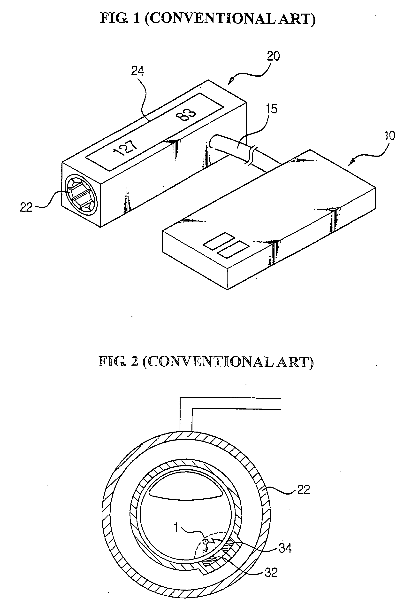
Since the light must travel a longer path, a wave pattern of the light transmitted to the light-receiving device 34 may be changed, thereby resulting in an inaccurate blood pressure index.
In addition, in a serious case, it may not be possible to measure the blood pressure.
However, in the conventional cuff for a blood pressure monitor, since the position during insertion of the finger may be not consistent, different measured values may be obtained, depending on the positioning of the finger, even under the same conditions.

Method used


Image

  • Cuff for blood pressure monitor
  • Cuff for blood pressure monitor
  • Cuff for blood pressure monitor

Examples


Embodiment Construction

[0032] Reference will now be made in detail to the embodiments of the present invention, examples of which are illustrated in the accompanying drawings, wherein like reference numerals refer to the like elements throughout. The embodiments are described below to explain the present invention by referring to the figures.

[0033]FIG. 4 is a perspective view of a cuff for a blood pressure monitor, according to an embodiment of the present invention, FIG. 5 is a front view of the cuff of FIG. 4, and FIG. 6 is a perspective view illustrating an example of using the cuff of FIG. 4.

[0034] Referring to FIGS. 4 and 5, a cuff 100 for a blood pressure monitor includes a cuff housing 110, a pressing part 120, and a cuff guide 130. The pressing part 120 is installed in the cuff housing 110 and disposed along the inner circumference of the cuff housing 110. Since the cuff housing 110 has an approximately cylindrical inner wall, the pressing part installed inside the cuff housing 110 may provide a...


PUM


Abstract

A cuff of a blood pressure monitor includes: a pressing part surrounding a first finger and pressing against the first finger by using air pressure; a cuff housing covering an outer circumference of the pressing part; and a cuff guide formed on a side surface of the cuff housing and in contact with a second finger adjacent to the first finger to guide positioning of the cuff housing. The cuff guide is formed corresponding to a shape of the second finger and maintains a desired positioning of the cuff housing, thus constraining insertion of the first finger at a predetermined angle. Accordingly, a position of an artery of the first finger inserted into the cuff with respect to a blood pressure sensing portion improves the accuracy of measuring the blood pressure.

Description

CROSS-REFERENCE TO RELATED APPLICATIONS [0001] This application claims the benefit of Korean Patent Application No. 2005-66042, filed on Jul. 20, 2005, in the Korean Intellectual Property Office, the disclosure of which is incorporated herein in its entirety by reference. BACKGROUND OF THE INVENTION [0002] 1. Field of the Invention [0003] The present invention relates to a cuff for a blood pressure monitor for a finger, and more particularly, to a cuff for a blood pressure monitor which improves the sensitivity with respect to blood pressure measurement, and is also convenient to use. [0004] 2. Description of the Related Art [0005]FIG. 1 is a perspective view illustrating a conventional a blood pressure monitor for a finger. [0006] Referring to FIG. 1, a conventional blood pressure monitor includes a main unit 10 and a cuff unit 20, and the main unit 10 is connected to the cuff unit by a cable 15. A display unit 24 is provided on the top of the cuff unit 20, in which a cuff for pres...

Claims


Application Information

Patent Timeline
IPC IPC(8): A61B5/02
CPCA61B5/02241A61B5/022
Inventor LEE, JONG YOUNKIM, KYUNG HOCHOE, EUN YOUNGJUNG, HYE JIN
Owner SAMSUNG ELECTRONICS CO LTD
Learn More