
Container with a non-drip pouring lip

Inactive Publication Date: 2007-01-25
MORIN
View PDF24 Cites 5 Cited by
  • Summary
  • Abstract
  • Description
  • Claims
  • Application Information

AI Technical Summary

Problems solved by technology

While such pouring spouts have gained a certain degree of acceptance, some still suffer from the disadvantage of allowing drips or drops to form when the container is raised upright after the dispensing step.

Method used


Image

  • Container with a non-drip pouring lip
  • Container with a non-drip pouring lip
  • Container with a non-drip pouring lip

Examples


Embodiment Construction

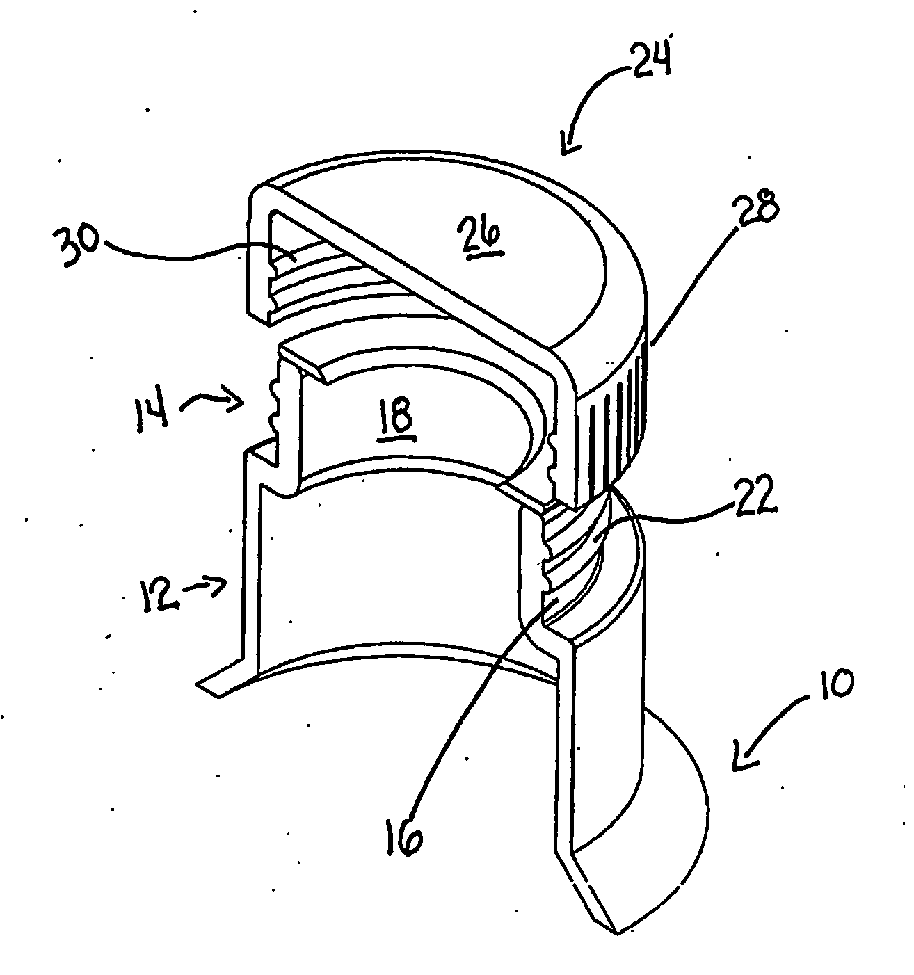
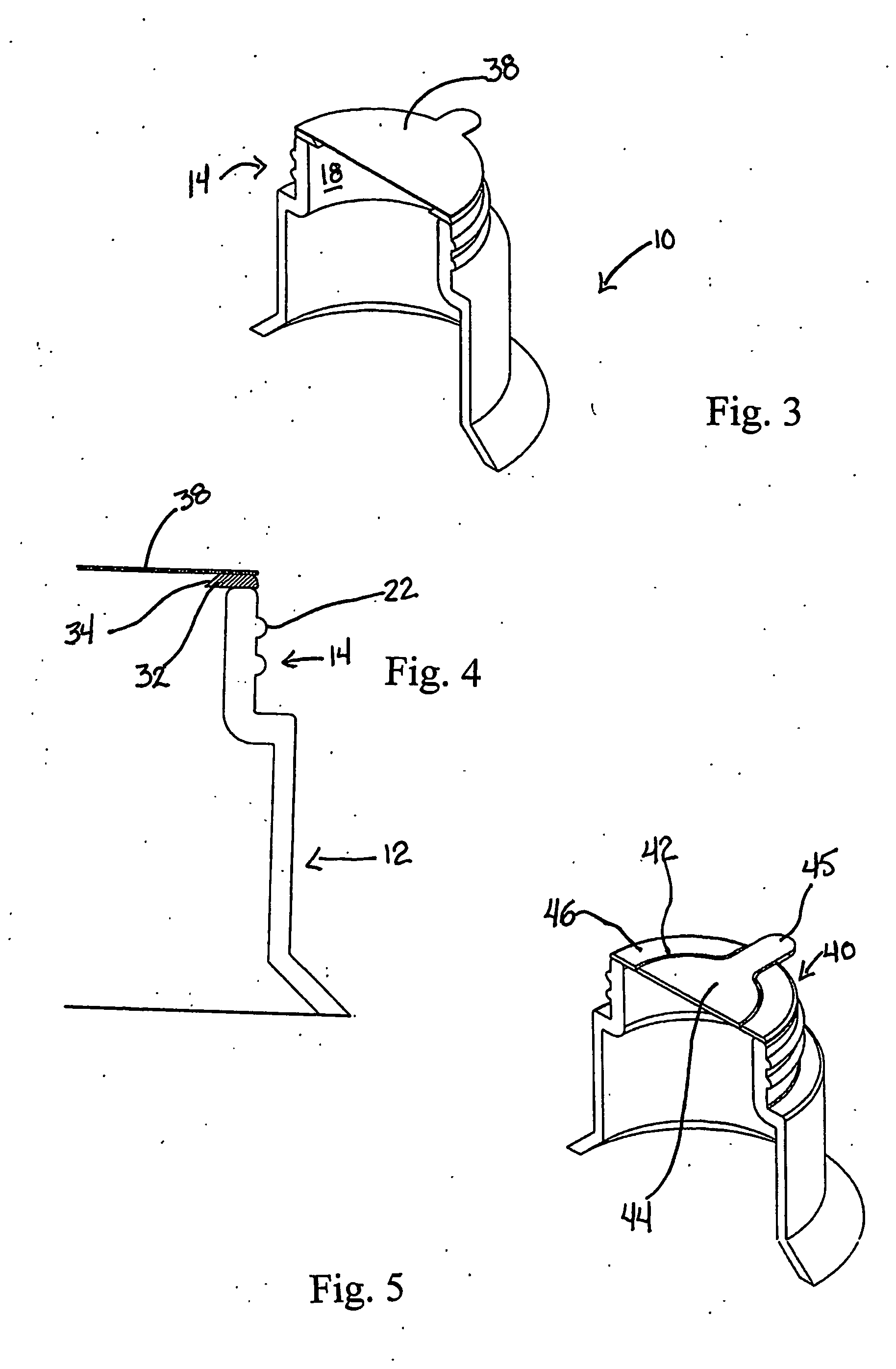
[0038] Referring to the drawings in greater detail and by reference characters thereto, it should initially be noted that since many different embodiments are disclosed herein, similar reference numerals are used for similar components although the appearance of the components may differ slightly. Thus, for example, in many of the embodiments, a single reference numeral will be utilized for the neck portion of the container although different configurations of necks are illustrated.

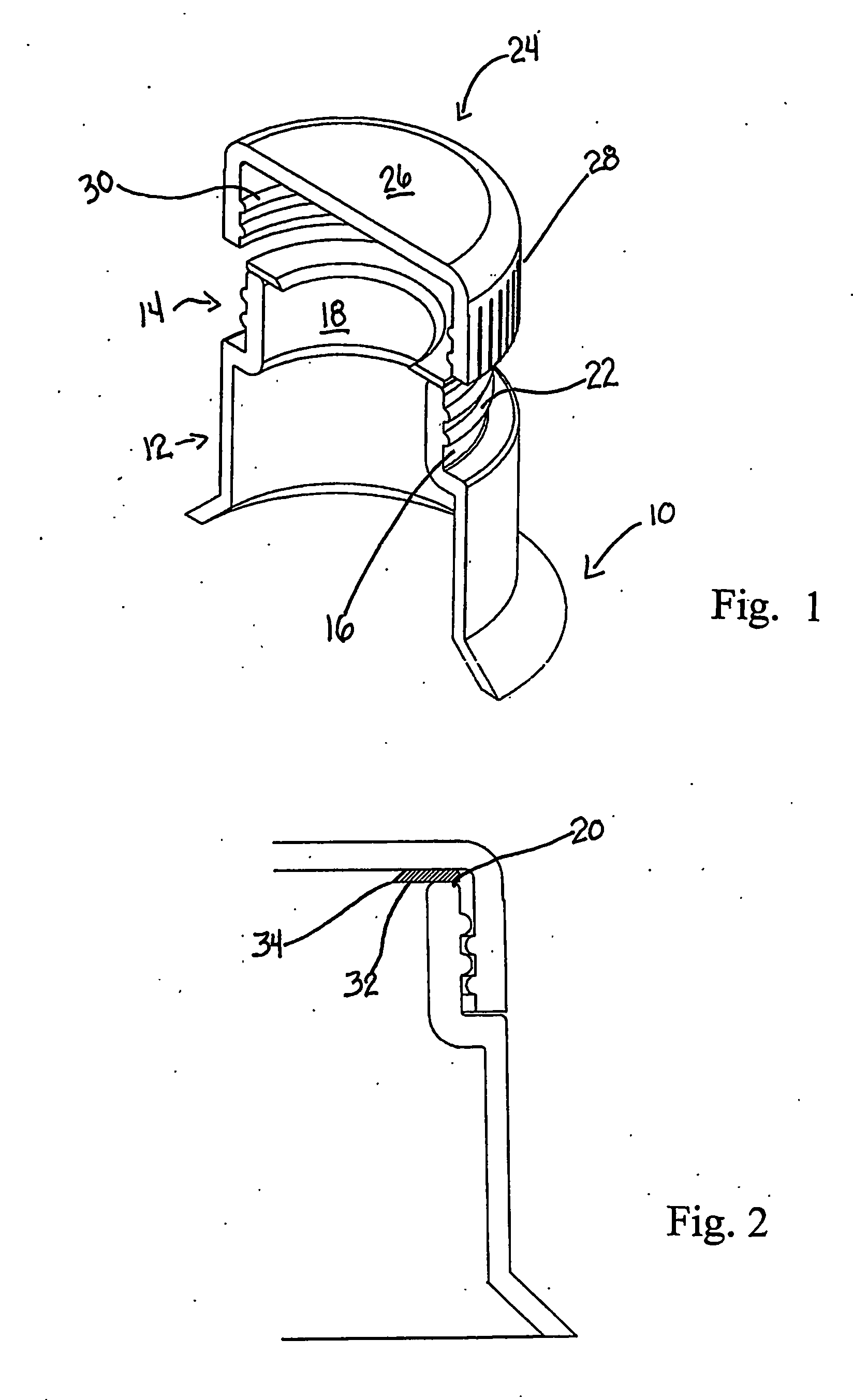
[0039] In FIG. 1, there is illustrated an upper portion of a container 10 and which container 10 includes a lower neck generally designated by reference numeral 12 and an upper neck generally designated by reference numeral 14. Upper neck 14 includes a neck outer surface 16, a neck inner surface 18 and a rim 20 extending therebetween.

[0040] Provided on the neck outer surface 16 are a plurality of outer threads 22. A cap 24 has a top wall 26 and a downwardly depending side wall 28. On the interior surfac...


PUM


Abstract

A container having a body portion (10) and a dispensing opening, a neck (14) surrounding said dispensing opening, the neck having a rim (20), an inner neck surface (18) and an outer neck surface (16), and a drip minimizing member (32, 68) extending inwardly over a portion of the dispensing outlet, the member being located proximate the rim (20), the member terminating in a sharp edge (34, 70) to minimize dripping when pouring from the container.

Description

FIELD OF THE INVENTION [0001] The present invention relates to containers and more particularly, relates to means for minimizing dripping when pouring a fluid from a container. BACKGROUND OF THE INVENTION [0002] The use of a pouring aid is well known in the art and such devices have been widely used in the pouring of various fluids. In particular, pouring aids to minimize dripping have been widely used for the dispensing of wine and the like. [0003] One approach which has been taken to minimize dripping is the use of a pouring spout which mounts on the neck of a container. While such pouring spouts have gained a certain degree of acceptance, some still suffer from the disadvantage of allowing drips or drops to form when the container is raised upright after the dispensing step. In order to overcome this, various proposals have been advanced in the art including, for example, a pouring spout, such as shown in U.S. Pat. No. 6,352,179 wherein the pouring spout is placed in the containe...

Claims


Application Information

Patent Timeline
IPC IPC(8): B65D5/72B65D23/06B65D41/62B65D47/40
CPCB65D23/06B65D47/40B65D41/62B65D23/065
Inventor MORIN, MICHEL
Owner MORIN
Learn More