
Interface suspension for alloy based laser welding

a technology of alloy based laser welding and interface suspension, which is applied in the direction of additives, lubricants, petroleum industry, etc., can solve the problems of poor welding results, poor weld quality, and difficult application and maintenance of copper metal foil in the specific area

Inactive Publication Date: 2007-01-18
DR IND
View PDF6 Cites 9 Cited by
  • Summary
  • Abstract
  • Description
  • Claims
  • Application Information

AI Technical Summary

Benefits of technology

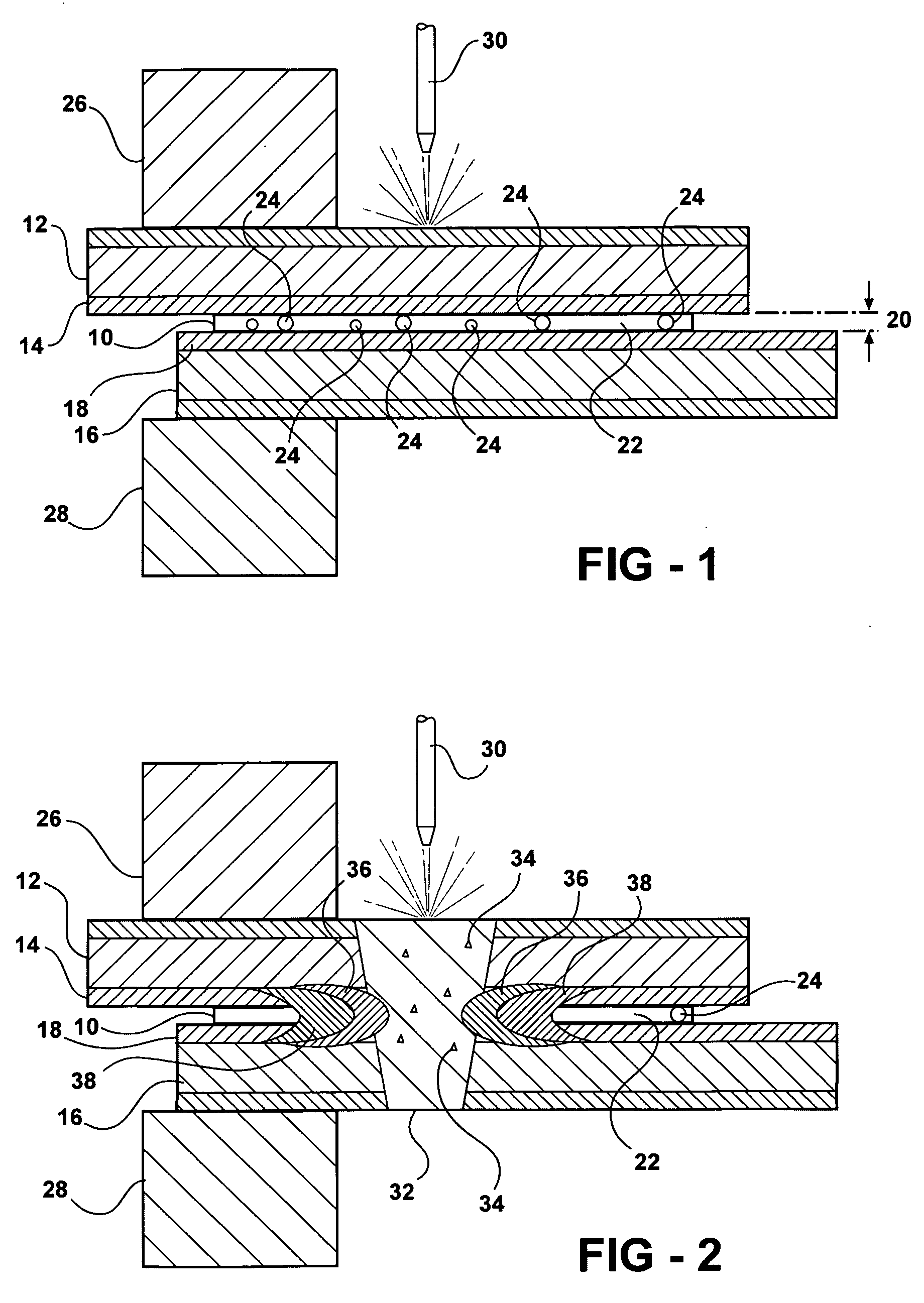
[0010] An interface suspension is disclosed for facilitating the laser welding of a first metal having a first zinc coating and a second metal having a second zinc coating. The interface suspension includes a petrolatum base. The interface suspension also includes a plurality of metal spherules suspended in the petrolatum base. The interface suspension melts when the laser welding occurs and allows the plurality of metal spherules to absorb vapors released by the first and second zinc coatings when the first and second zinc coatings boil.

Problems solved by technology

When the parts being welded are galvanized steel, there is a potential for poor weld quality if the source of heat is elevated rapidly and concentrated in a specific area.
The poor welding results occur because a laser weld occurs rapidly and the vaporization of certain materials in the weld area are trapped within the molten material created by the laser beam.
This method is, however, cumbersome in that copper metal foil is difficult to apply and maintain in the specific area that is to be welded.
In addition, much of the copper is not used and, therefore, wasted during the laser welding process.
This method of introducing an intermediate material to facilitate the welding of two galvanized sheets of metal is cumbersome for several reasons.
First, it is difficult to control the application of an oil on a sheet of galvanized metal when the surface to which the oil is being applied is not horizontal.
Another disadvantage of the oil / copper powder combination is the size of the particulate is so small that it does not create a gap between the two sheets of metal being welded.
In addition, particulate that makes up a powder has no defined shape because the powder is created in a pulverization process.
Any type of consistency in separation, if separation were possible, would not be consistent.
Because the oil and copper powder are so small and fluid, the two sheets of galvanized steel may be too close together to facilitate a proper, non-violent weld.

Method used


Image

  • Interface suspension for alloy based laser welding

Examples


Embodiment Construction

[0014] The invention is an interface suspension 10. The interface suspension 10 is used to facilitate laser welding of a first metal 12 having a first zinc coating 14 to a second metal 16 having a second zinc coating 18. In the embodiment shown, the first metal 12 and the second metal 16 are steel sheet metal that are coated with zinc on both sides. It should be appreciated by those skilled in the art that the first 12 and second 16 metal pieces may be other forms of metal fabricated from metal others than steel and may only be partially coated with zinc. The zinc coatings 14, 18 are used to inhibit corrosion of the base component, i.e., the first 12 and second 16 metals. This combination of a zinc coated steel piece of steel is commonly referred to as galvanized steel.

[0015] Due to the low melting and boiling points of zinc, the zinc in the first 14 and second 18 coatings is vaporized quickly when subjected to laser welding procedures. The vapors created at the weld position are t...


PUM

PropertyMeasurementUnit
diametersaaaaaaaaaa
diametersaaaaaaaaaa
temperatureaaaaaaaaaa

Abstract

An interface suspension is disclosed for facilitating the laser welding of a first metal having a first zinc coating and a second metal having a second zinc coating. The interface suspension includes a petrolatum base. The interface suspension also includes a plurality of metal spherules suspended in the petrolatum base. The interface suspension melts when the laser welding occurs and allows the plurality of metal spherules to absorb vapors released by the first and second zinc coatings when the first and second zinc coatings boil.

Description

BACKGROUND ART [0001] 1. Field of the Invention [0002] The invention relates generally to a laser welded joint. More particularly, the invention relates to a suspension applied to a welded joint to facilitate the welding thereof. [0003] 2. Description of the Related Art [0004] Welding is the process of using heat to join two components together. In some instances, pressure is used in the process. In other methods, a third material is used. The process of welding components together is a very effective process when assembling structures because the resulting union of the parts is as strong or stronger than it would have been using other means to fasten the parts together. [0005] Another reason why parts are welded together as opposed to other means is due to the aesthetic result of welding. When finished, the parts joined together often look like a single part. This provides a look that is pleasing. In some instances, this enhanced look can also be useful in a functional sense. This ...

Claims


Application Information

Patent Timeline
Patent Type & Authority Applications(United States)
IPC IPC(8): C10M125/04
CPCC10M169/04C10M2201/05C10M2205/163C10N2240/402C10N2210/08C10N2220/021C10N2220/082C10N2210/01C10N2020/04C10N2010/14C10N2020/06C10N2010/02C10N2040/24C10N2010/16
Inventor NAUMOVSKI, VANCHOCATANESCU, DRAGOS
Owner DR IND
Learn More