
Strain modulation employing process techniques for CMOS technologies

Active Publication Date: 2007-01-18
TEXAS INSTR INC
View PDF5 Cites 40 Cited by
  • Summary
  • Abstract
  • Description
  • Claims
  • Application Information

AI Technical Summary

Benefits of technology

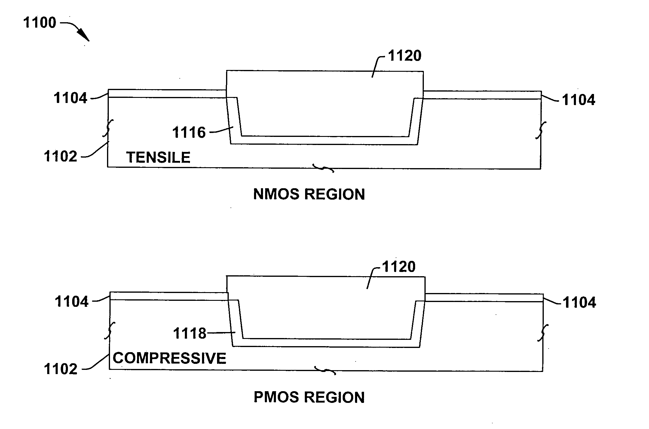
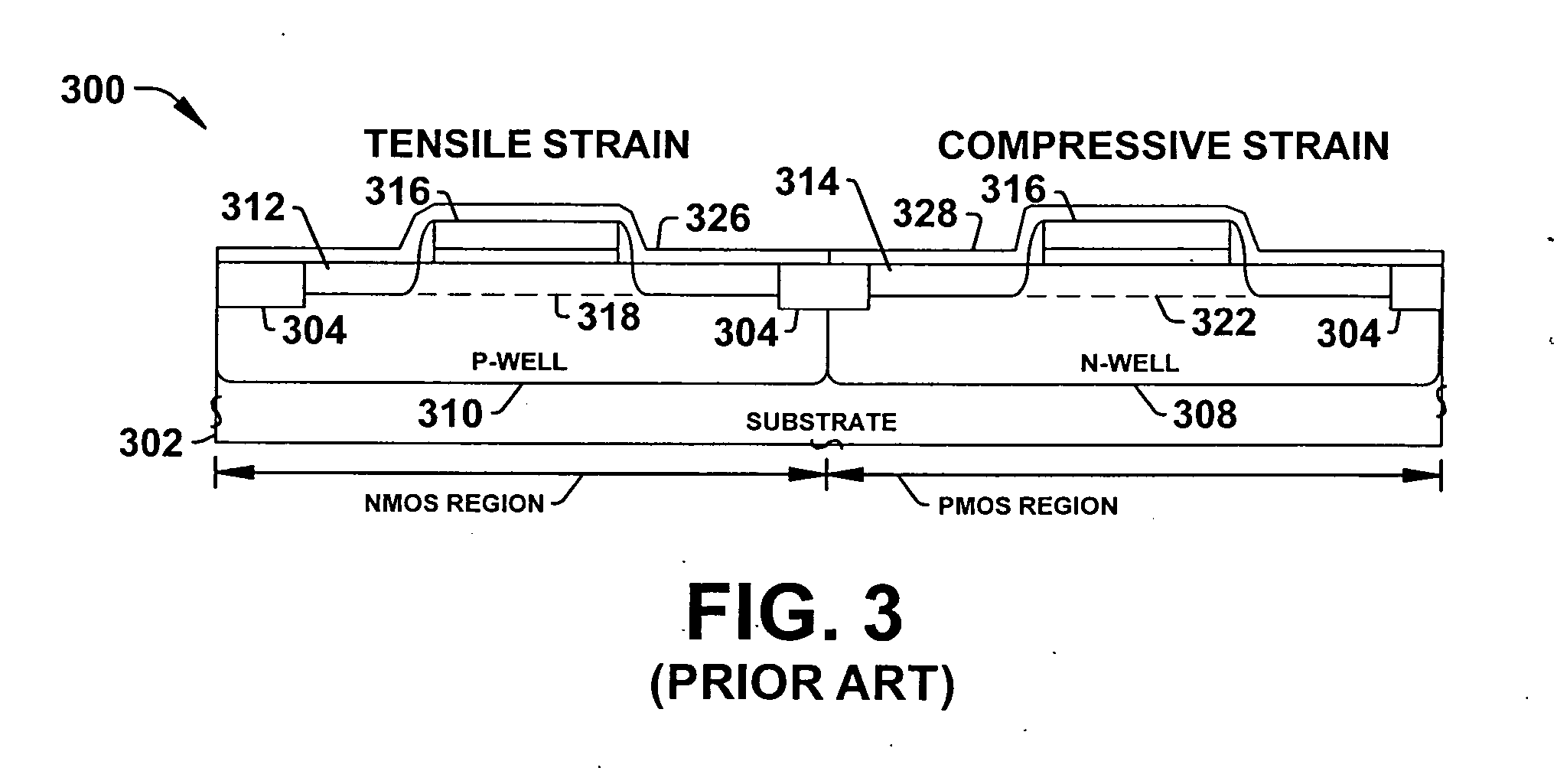
[0005] The present invention facilitates semiconductor device performance, particularly drive current, by fabricating stress inducing layers that can be modulated to selectively yield a different type of stress and / or amount. Compressive type strain / stress improves performance of NMOS devices but degrades performance of PMOS devices. Similarly, tensile type strain / stress improves performance of PMOS devices, but degrades performance of NMOS devices. By fabricating and employing modifiable / modulatable strain inducing layers, different portions of the strain inducing layer can induce varied strain types and / or amounts. Accordingly, compressive type strain can be induced in NMOS channel regions and tensile type strain can be induced into PMOS channel regions with the same strain inducing layer.

Problems solved by technology

Compressive type strain / stress improves performance of NMOS devices but degrades performance of PMOS devices.
Similarly, tensile type strain / stress improves performance of PMOS devices, but degrades performance of NMOS devices.

Method used


Image

  • Strain modulation employing process techniques for CMOS technologies
  • Strain modulation employing process techniques for CMOS technologies
  • Strain modulation employing process techniques for CMOS technologies

Examples


Embodiment Construction

[0019] One or more aspects of the present invention are described with reference to the drawings, wherein like reference numerals are generally utilized to refer to like elements throughout, and wherein the various structures are not necessarily drawn to scale. It will be appreciated that where like acts, events, elements, layers, structures, etc. are reproduced, subsequent (redundant) discussions of the same may be omitted for the sake of brevity. In the following description, for purposes of explanation, numerous specific details are set forth in order to provide a thorough understanding of one or more aspects of the present invention. It may be evident, however, to one of ordinary skill in the art that one or more aspects of the present invention may be practiced with a lesser degree of these specific details. In other instances, known structures are shown in diagrammatic form in order to facilitate describing one or more aspects of the present invention.

[0020] The present inven...


PUM

PropertyMeasurementUnit
Dielectric polarization enthalpyaaaaaaaaaa
Tensile strainaaaaaaaaaa
Tensile propertiesaaaaaaaaaa

Abstract

A method forms a semiconductor device comprising a modifiable strain inducing layer. A semiconductor body is provided. First and second regions of the semiconductor body are identified. A modifiable tensile strain inducing layer is formed over the device within the first and second regions. A mask is then formed that exposes the second region and covers the first region. A material is selected for a modification implant and the selected material is implanted into the second region thereby converting a portion of the modifiable tensile strain inducing layer into a compressive strain inducing layer within the PMOS region.

Description

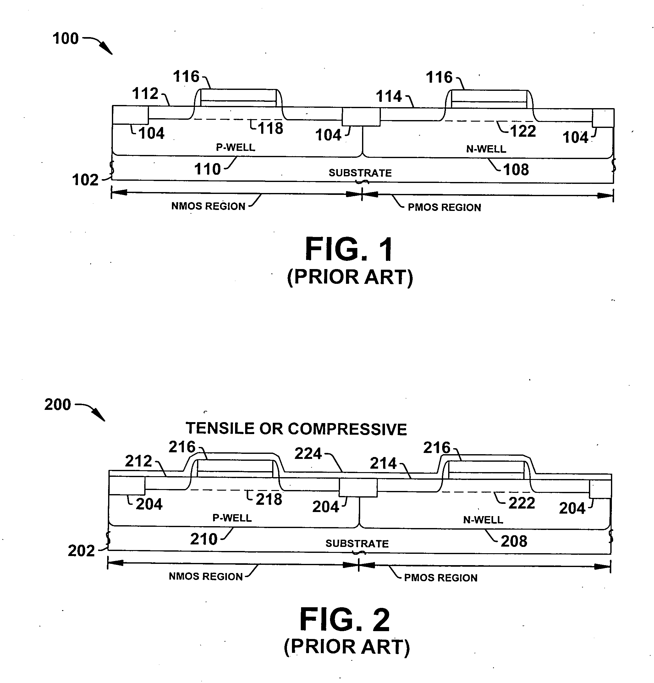
FIELD OF INVENTION [0001] The present invention relates generally to semiconductor devices and more particularly to methods for fabricating and modulating stress inducing layers for NMOS and PMOS semiconductor devices. BACKGROUND OF THE INVENTION [0002] It can be appreciated that placing mechanical stresses or strain (e.g., tension or compression) upon a semiconductor substrate can affect the performance of devices formed in and / or on the substrate. With regard to MOS transistors, for example, stressing the substrate can change charge mobility characteristics in respective channel regions of the transistors. This may be beneficial because, for a given electric field developed across the transistors, the amount of current that flows through the channel regions is directly proportional to the mobility of carriers in the channel regions. Thus, the higher the mobility of the carriers in the channel regions, the more rapidly the carriers will pass through the channel regions and the fast...

Claims


Application Information

Patent Timeline
IPC IPC(8): C12P21/06
CPCH01L21/265H01L21/823807H01L29/7846H01L29/7843H01L21/823878
Inventor MEHTA, NARENDRA SINGHBATHER, WAYNE ANTHONYVARGHESE, AJITH
Owner TEXAS INSTR INC
Learn More