
Accurate microstepping motor

a micro-stepping motor and accurate technology, applied in the field of accurate micro-stepping motors, can solve the problems of increasing the load of the motor, unable to improve the step accuracy, and the micro-steps are not guaranteed to be equal in size, so as to reduce the detent torque, increase the detent position, and pass easily

Active Publication Date: 2007-01-18
LIN ENG INC
View PDF25 Cites 19 Cited by
  • Summary
  • Abstract
  • Description
  • Claims
  • Application Information

AI Technical Summary

Benefits of technology

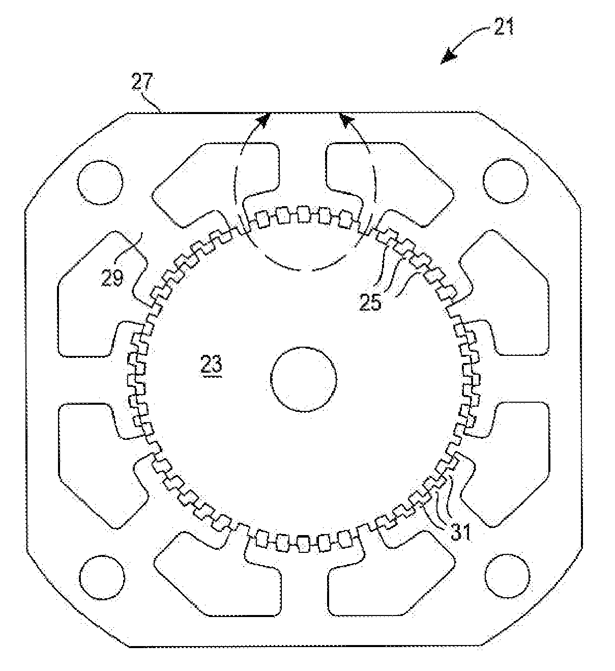
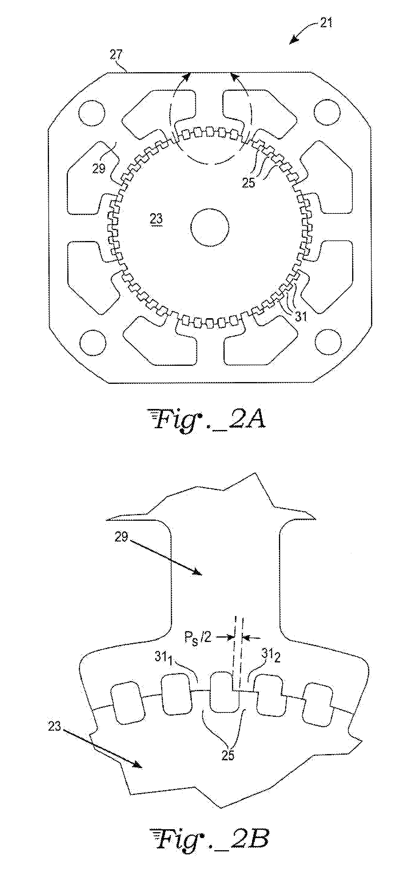
[0010] The present invention is a hybrid stepper motor in which the teeth on the stator poles are separated in groups with special pitch angles in order to rearrange the relationship between rotor and stator teeth to avoid teeth alignment at any one-phase ON or two-phase ON stable position. The pitch that is standard for all groups of stator pole teeth is Ps=2×θ×p, where θ is the full step angle and p is the number of bipolar phases of the motor. For an even number of teeth on each stator pole, the teeth are divided into groups 1 and 2 that are separated by a special pitch angle Pe=Ps±θ / 2. For an odd number of teeth on each stator pole, the teeth are divided into groups 1, M, and 2, where groups 1 and 2 teeth are separated from group M middle teeth by a special pitch angle Po=Ps±θ / 4. The overall effect of the stator tooth repositioning is to create an additional detent position between each of the prior phases, thereby doubling the number of detent positions and reducing the detent torque by approximately half. These detent positions are not in line with the one-phase ON or two-phase ON stable positions. The motor will more easily pass through the natural detent positions, thus providing better step accuracy and smoother motion.

Problems solved by technology

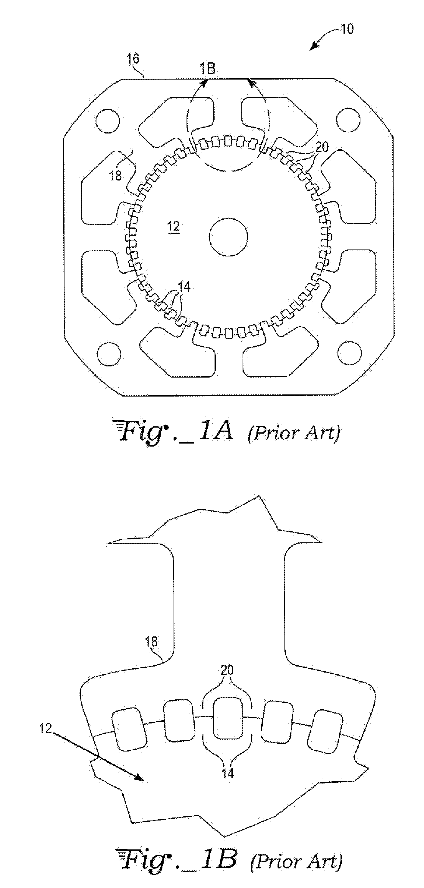
For example, mechanical damping has been used to smooth out the motion, but it also adds load to the motor and cannot improve step accuracy.
However, unlike the full-step positions, the micro-steps are not guaranteed to be equal in size.
Because of detent torque, coil inductance, pole geometry, and other factors, even if the drive current waveform applied to the stator coils should happen to be perfectly sinusoidal in form, a perfectly linear response by the motor will generally not be achieved.
The rotor has greater difficulty pulling out from these stable positions, which typically results in erratic jerks in rotor motion.
While all of these various approaches achieve some degree of smoothing of stepper motion and noise reduction, the smoothing is typically accompanied by some reduction in microstepping accuracy or in holding torque, or other performance factor, as a tradeoff.

Method used


Image

  • Accurate microstepping motor
  • Accurate microstepping motor
  • Accurate microstepping motor

Examples


example 1

[0027] A 7.2° standard stator tooth pitch angle corresponds to a 1.8° 2-phase bi-polar (or 4-phase unipolar) motor, a 1.2° 3-phase bipolar (or 6-phase unipolar) motor, a 0.72° 5-phase bipolar (or 10-phase unipolar) motor, where 1.8°, 1.2°, and 0.72° refer to the full step angle θ of the respective motors. For a 1.8° 2-phase bipolar (or 4-phase unipolar) motor, the stator teeth have tooth separations Pe between the two groups of stator teeth of 7.2°±1.8° / 2=7.2°±0.9°; i.e., alternately 6.3° and 8.1°. For a 1.2° 3-phase bipolar (or 6-phase unipolar) motor, the stator teeth have tooth separations Pe between the two groups of stator teeth of 7.2°±1.2° / 2=7.2°±0.6°; i.e., alternately 6.6° and 7.8°. And for a 0.72° 5-phase bipsolar (or 10-phase unipolar) motor, the stator teeth have tooth separations Pe between the two groups of stator teeth of 7:2°±0.72° / 2=7.2°±0.36°; i.e., alternately 6.84° and 7.56°.

[0028] With reference to FIGS. 4A and 4B, another exemplary stepper motor 41 in accordan...

example 2

[0029] As before, a 7.2° standard stator tooth pitch angle corresponds to a 1.8° 2-phase bipolar (or 4-phase unipolar) motor, a 1.2° 3-phase bipolar (or 6-phase unipolar) motor, a 0.72° 5-phase bipolar (or 10-phase unipolar) motor, where 1.8°, 1.2°, and 0.72° refer to the full step angle θ of the respective motors. For a 1.8° 2-phase bipolar (or 4-phase unipolar) motor, the stator teeth have tooth separations Po for the three groups of stator teeth of 7.2°±0.9° / 2 7.2°±0.45°=6.75° or 7.65°. For a 1.2° 3-phase bipolar (or 6-phase unipolar) motor, the stator teeth have tooth separations Po between the two groups of stator teeth of 7.2°±0.6° / 2=7.2°±0.3°=6.9° or 7.5°. And for a 0.72° 5-phase bipolar (or 10-phase unipolar) motor, the stator teeth have tooth separations Po between the two groups of stator teeth of 7.2°±0.36° / 2=7.2°±0.18°=7.02° or 7.38°.

[0030] With reference to FIG. 5, the effect of the tooth offsets is to double the number of detent positions while reducing the amount of ...


PUM


Abstract

A stepper motor includes a rotor having equally spaced rotor teeth defining a full step angle, and a stator with stator poles wound with coils that can be driven in a series of phases so as to magnetically interact with the rotor to produce stepping motion. The stator poles have teeth organized into two groups when there is an even number of stator teeth per pole, or into three groups for an odd number of stator teeth per pole. The stator teeth have an average pitch different from the rotor's tooth pitch, but the groups of stator teeth are also displaced relative to other groups by a specified offset angle of one-half or one-quarter step to double the number of detent positions, and to displace such detent positions from full one-phase ON or two-phase ON positions.

Description

CROSS-REFERENCE TO RELATED APPLICATION [0001] The present application claims priority under 35 U.S.C. 119(e) from U.S. provisional application no. 60 / 699,5360, filed Jul. 15, 2005.TECHNICAL FIELD [0002] The invention relates generally to electric motor structures designed to rotate step by step, i.e., stepper motors, and in particular to arrangements, including microstepping, for smoothing out the motion, as well as arrangements for improving step accuracy. BACKGROUND ART [0003] Stepper motors are used in a wide variety of applications that require precise motion control, such as in printers, scanners, x-y tables, turntables, tape and disk drive systems, security cameras and other optical equipment robotics, CNC (computer-numeric-control) machine tools, dispensers, and injector pumps. Unlike “conventional” AC or DC motors, which produce continuous rotary motion from a continuously applied input voltage, stepper motors will stay indefinitely at a particular stable “detent” position a...

Claims


Application Information

Patent Timeline
Patent Type & Authority Applications(United States)
IPC IPC(8): H02K37/14
CPCH02K37/18
Inventor BADGEROW, RICHARD L.LIN, TED T.
Owner LIN ENG INC
Learn More