
Cable organizer

a cable organizer and connector technology, applied in the field of cable organizers, can solve the problems of difficult or impractical inconvenient repositioning of electronic devices, and difficulty in identifying and locating appropriate connectors, and achieve the effect of convenient cable connection

Inactive Publication Date: 2007-01-18
STORK MICHAEL
View PDF23 Cites 1 Cited by
  • Summary
  • Abstract
  • Description
  • Claims
  • Application Information

AI Technical Summary

Benefits of technology

[0015] In another of its aspects, the invention includes a kit for organizing cables associated with an electronic device. The kit includes a body having a reflective surface and a number of apertures for receiving and locating the cables in a predetermined arrangement. Also, the kit includes one or more light assemblies receivable in at least one of the apertures for illuminating at least a portion of the electronic device and for use with the reflective surface to facilitate the connection of the cables to the electronic device. The apparatus also includes one or more bases including a mating portion receivable in one or more of the apertures for supporting the body in a predetermined position.

Problems solved by technology

The difficulty with this configuration is that the back wall and the connectors typically are not readily accessible by a user.
In these circumstances, the user has difficulty identifying and locating the appropriate connector for any particular cable.
However, repositioning of the electronic device is often inconvenient, difficult or impractical.

Method used


Image

  • Cable organizer
  • Cable organizer
  • Cable organizer

Examples


Embodiment Construction

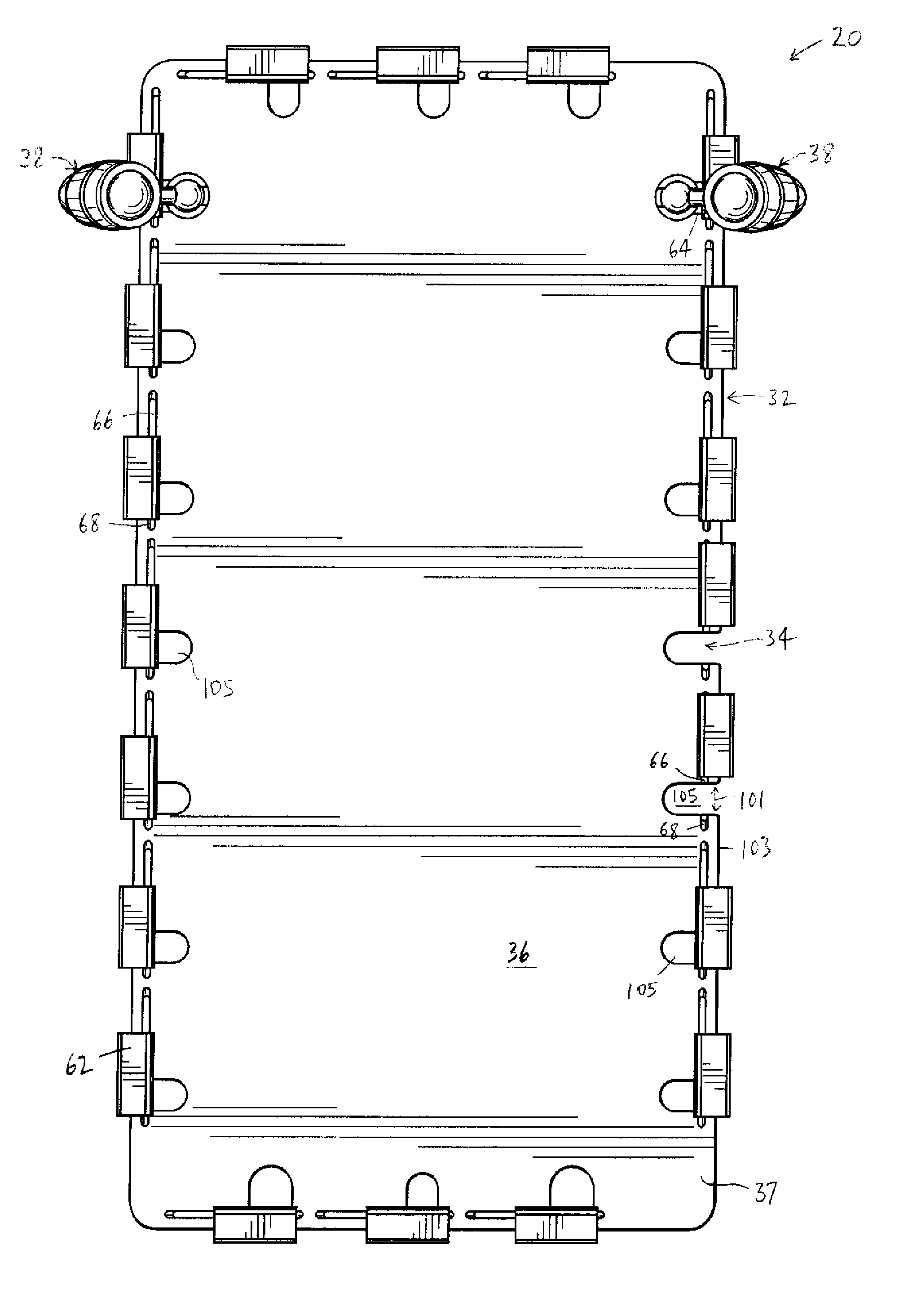
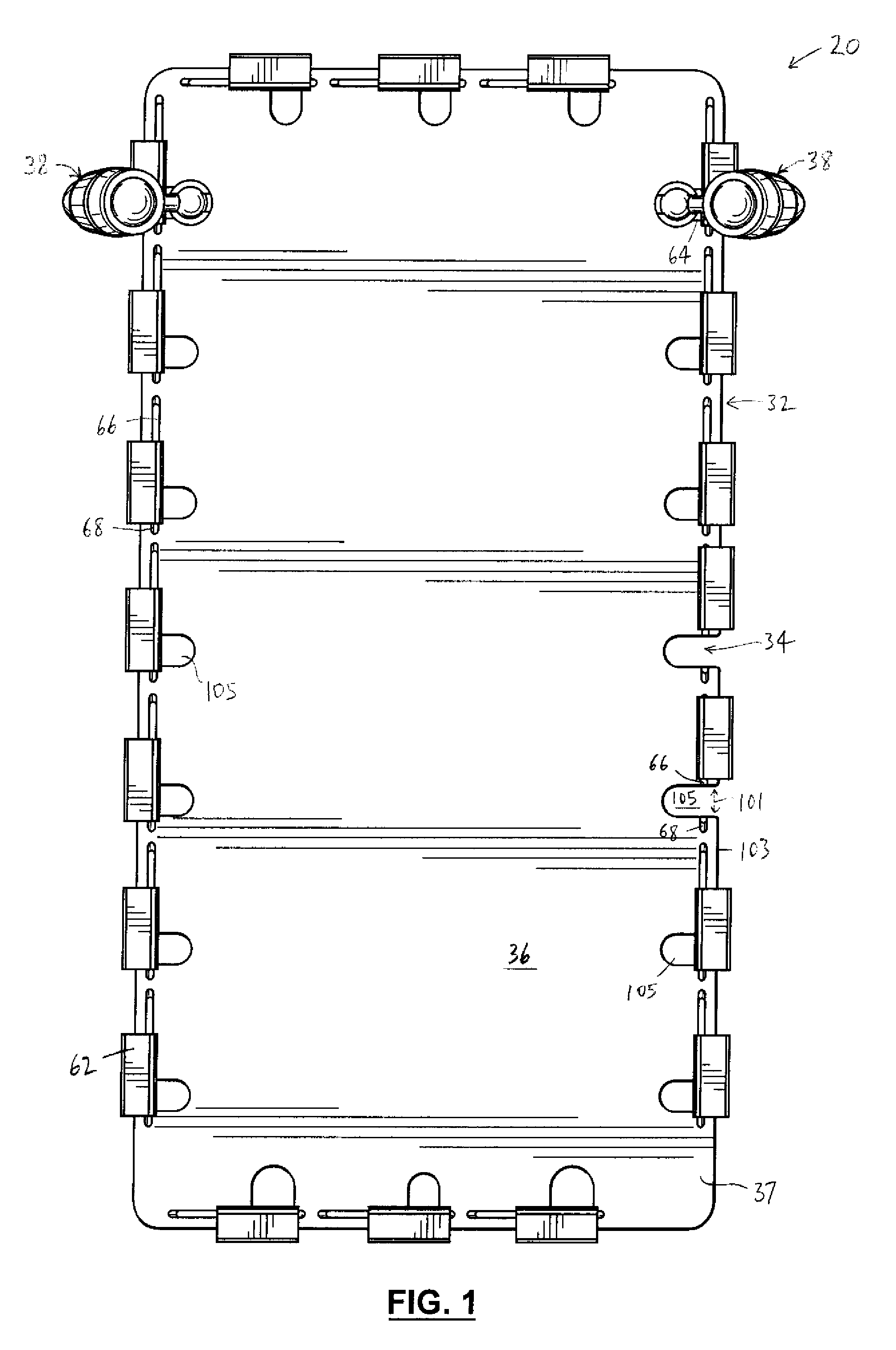
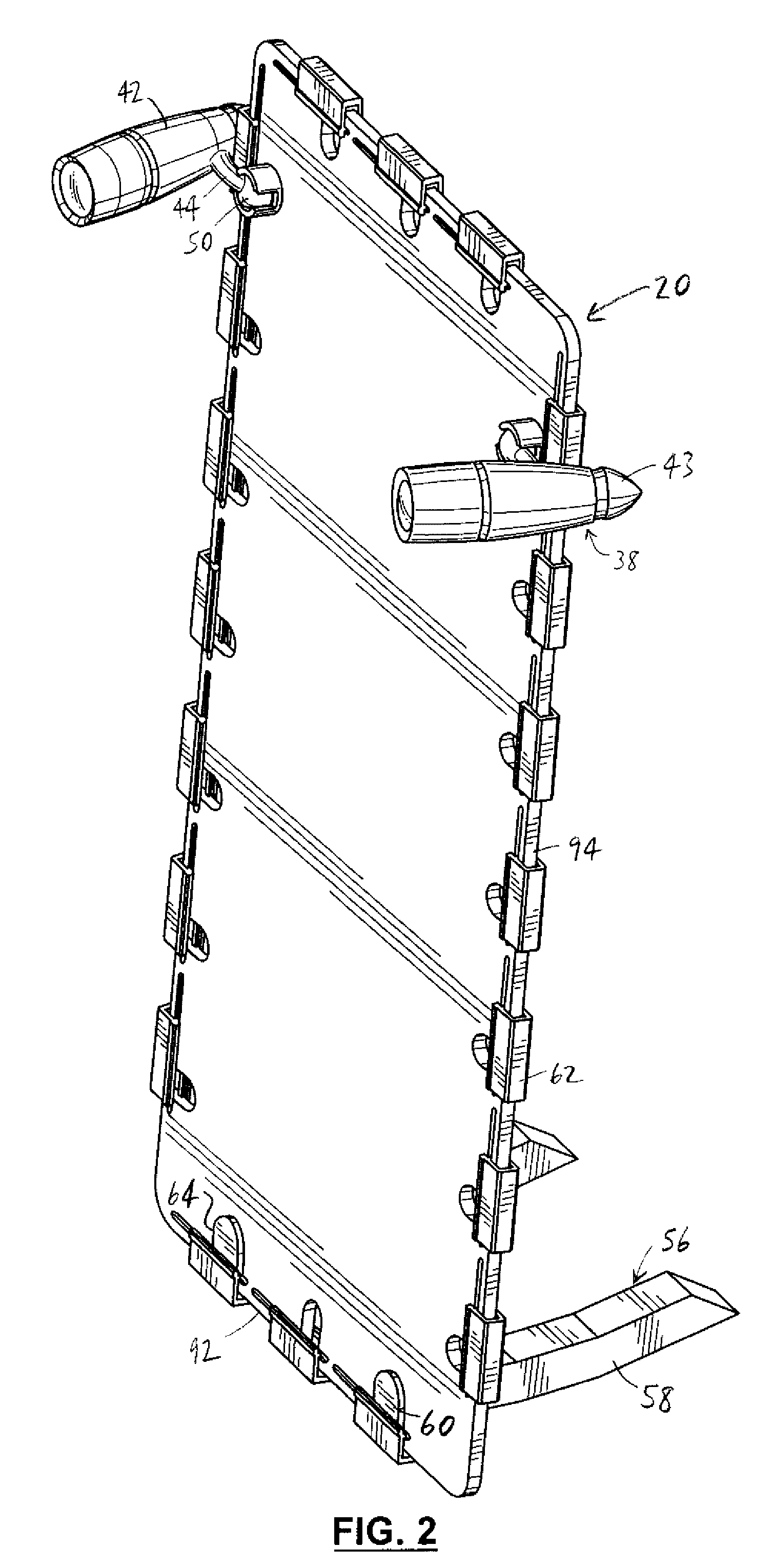
[0026] Reference is first made to FIGS. 1-3, 3A, 3B, 3C, and 6 to describe an embodiment of an apparatus in accordance with the invention indicated generally by the numeral 20. As can be seen in FIG. 6, the apparatus 20 is for organizing a plurality of cables 22 with respective ends 24 for use with an electronic device 26 with one or more back walls 28. The back wall 28 has connectors (not shown) positioned thereon in which the ends 24 are connectable. The apparatus 20 includes a body 32 with apertures or slots 34 for positioning each cable 22 respectively in a predetermined arrangement (FIGS. 1, 6). Also, the apparatus preferably includes one or more reflective surfaces 36 for use in inserting the ends 24 of the cables 22 in the connectors respectively on the back wall 28. The reflective surface is preferably disposed on a front side 37 of the body 32.

[0027] As will be described, it is preferred that the apparatus 20 includes one or more light sources 38 for use with the reflectiv...


PUM


Abstract

An apparatus for organizing a number of cables with respective bodies connected to ends thereof for use with an electronic device with a back wall. The back wall has a number of connectors with which the ends of the cables are connectable. The apparatus includes a body having a number of apertures for positioning each cable respectively in a predetermined arrangement. The apparatus also includes one or more reflective surfaces for use in inserting the ends of the cables in the connectors respectively on the back wall.

Description

BACKGROUND OF THE INVENTION [0001] Electronic devices such as personal desktop computers, home theatres and other multimedia systems typically include a multitude of cables to connect the electronic device to peripheral components such as speakers, controllers, and other components. For instance, in the case of a desktop computer, the result is a series of cables that are received in connectors on a back wall of the main processor housing and connect the electronic device to components including the monitor, the keyboard and the mouse. [0002] The difficulty with this configuration is that the back wall and the connectors typically are not readily accessible by a user. In these circumstances, the user has difficulty identifying and locating the appropriate connector for any particular cable. [0003] In many circumstances, such as when installing new hardware or making changes to existing configurations, it is necessary to connect or disconnect the cables of the electronic device. Wher...

Claims


Application Information

Patent Timeline
Patent Type & Authority Applications(United States)
IPC IPC(8): H02B1/015H02B1/40
CPCA47B21/06H02G3/32H01R13/72H02G3/00H05K7/00
Inventor LEFEBVRE, DENNIS A.BANNON, DAVID L.
Owner STORK MICHAEL
Learn More