
Terminal fitting

a technology of terminal fittings and metal blanks, applied in the direction of coupling contact members, coupling device connections, electrical devices, etc., can solve the problem of reducing the yield of terminal fittings from the metal blank, and achieve the effect of correcting the posture of the ceiling pla

Inactive Publication Date: 2007-01-11
SUMITOMO WIRING SYST LTD
View PDF6 Cites 4 Cited by
  • Summary
  • Abstract
  • Description
  • Claims
  • Application Information

AI Technical Summary

Benefits of technology

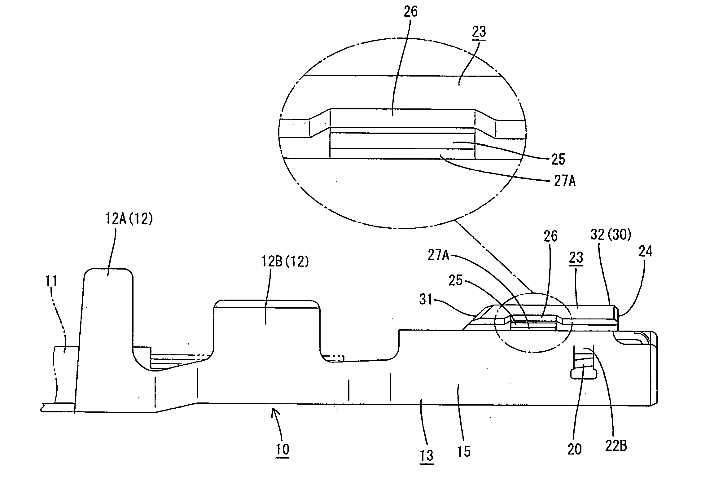
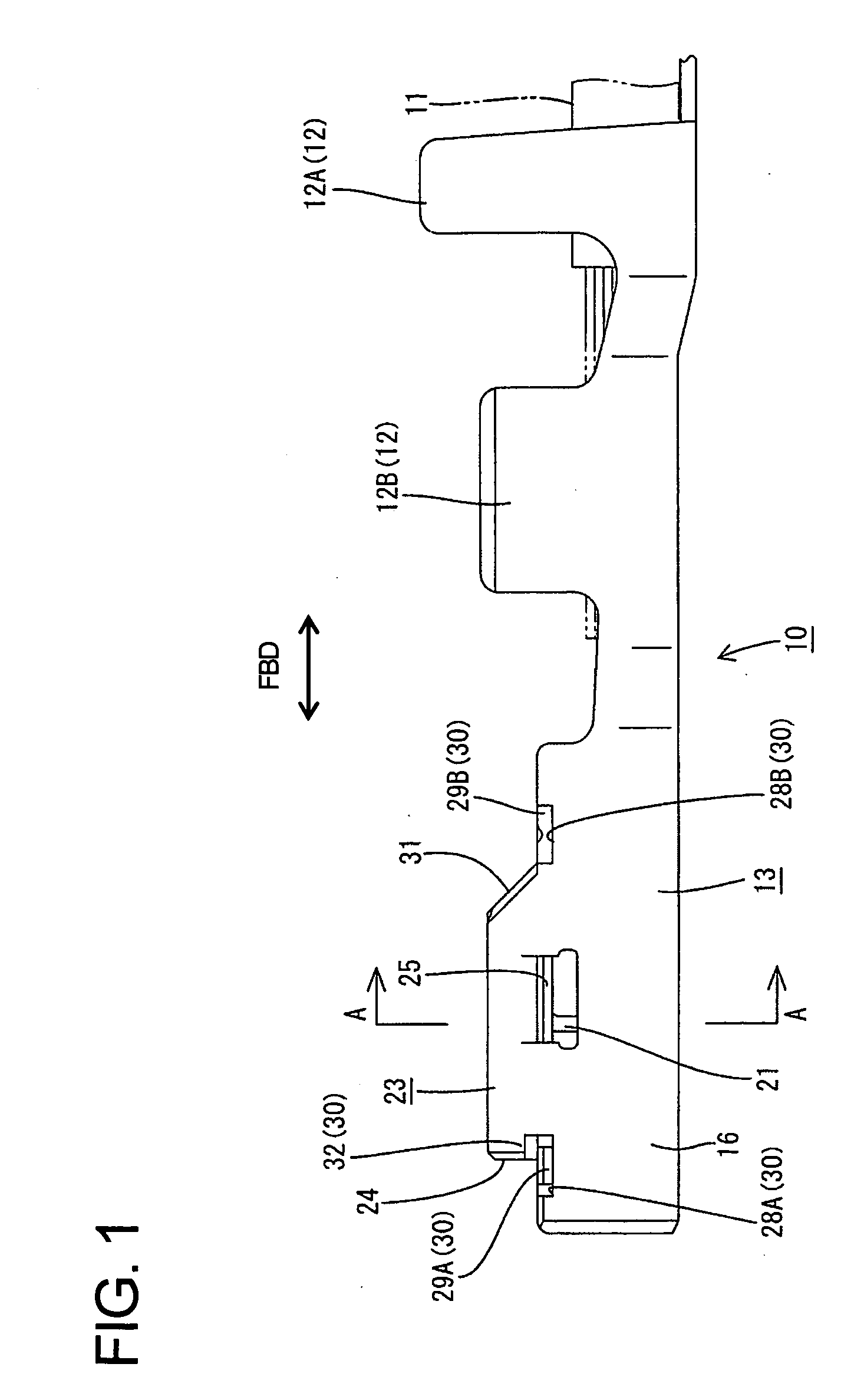
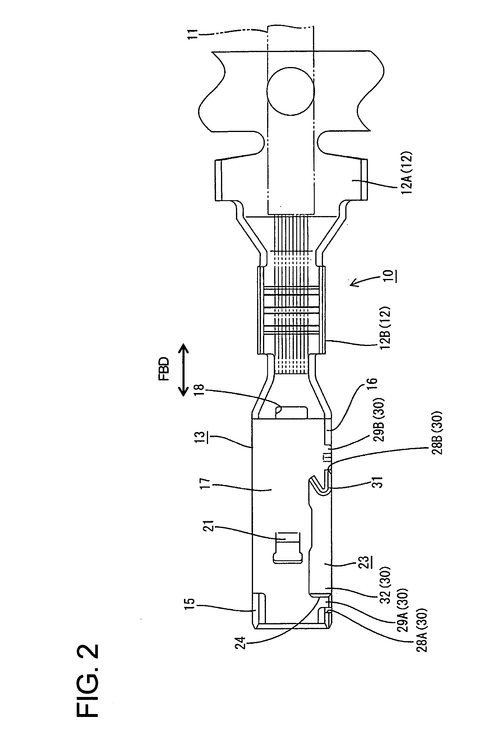
[0008] The invention is a terminal fitting with a tube that has first and second side plates and a ceiling plate bent from a top end of the first side plate towards the second side plate. The second side plate has at least one standing portion that stands more outward than a connected portion of the second side plate with the ceiling plate. At least one pressing portion is bent inward from an intermediate height of the standing portion and is placed on the outer surface of the ceiling plate. Placement of the pressing portion on the outer surface of the ceiling plate prevent an opening deformation of the ceiling plate and corrects the posture of the ceiling plate even if the tube is twisted.
[0010] A detecting portion preferably is formed by bending the upper end of the standing portion inwardly and can be contacted by a probe for testing an electrical connection of the terminal fitting. The probe for an electrical connection test can be brought easily into contact with an area where the standing portion is bent. Therefore the precision of the electrical connection test for the terminal fitting can be improved.
[0012] At least one of the lift preventing portions is formed with at least one recess at or near the upper edge of the second side plate. At least one projecting piece is provided at or near an end edge of the ceiling plate and can fit into the recess. The projecting piece is crimped, bent, folded or deformed into connection with side walls of the recess. Accordingly, a member provided above the upper plate to preventing a lift of the upper plate can be omitted at least in the area of the lift preventing portion. Therefore, a yield of the terminal fittings can be improved.
[0015] A resilient contact preferably is provided in the tube for contacting a mating terminal fitting. At least one auxiliary resilient piece preferably is provided and engages the resilient contact when the mating terminal fitting is inserted into the tube. Thus, the auxiliary resilient piece improves the rigidity of the resilient contact.

Problems solved by technology

As a result, a projecting distance of the extension on the metal blank is long and leads to a reduced a yield of terminal fittings from the metal blank.

Method used


Image

  • Terminal fitting
  • Terminal fitting
  • Terminal fitting

Examples


Embodiment Construction

[0025] A female terminal fitting 10 according to a first embodiment of the invention is described with reference to FIGS. 1 to 7, and is formed unitarily by punching, pressing, stamping, embossing, folding and / or bending an electrically conductive metal plate. The female terminal fitting 10 has a front end for connection with a mating male terminal fitting and a rear end opposite the front end. A barrel 12 is formed at the rear end of the female terminal fitting 10 and is configured for connection with an end of a wire 11. A tube 13 is formed at the front end and is continuous with the barrel 12. The terms top and bottom are used herein to provide a convenient frame of reference, but are not intended to imply a required gravitational orientation. In this context, reference is made to FIGS. 5 and 6 concerning the vertical direction.

[0026] The barrel 12 includes an insulation barrel 12A to be crimped, bent or folded into connection with an insulation coating of the wire 11 and a wire...


PUM


Abstract

A terminal fitting (10) has a rectangular tube (13) with opposed first and second side plates (15, 16). A upper plate (17) is bent from the first side plate (15) into contact with the second side plate (16). A standing portion (23) stands up from the second side plate (16) and a pressing portion (25) is bent from the standing portion (23) and placed on the outer surface of the upper plate (17) to prevent the upper plate (17) from lifting. The pressing portion (25) is formed within a projecting range of the standing portion (23) to improve a yield of a punching operation from a metal plate.

Description

BACKGROUND OF THE INVENTION [0001] 1. Field of the Invention [0002] The invention relates to a terminal fitting and to a method of forming it. [0003] 2. Description of the Related Art [0004] Japanese Unexamined Patent Publication No. 2000-200667 discloses a terminal fitting with a rectangular tube that has opposed first and second side plates and a top plate that is bent from an upper end of the first side plate. A groove is formed in the second side plate, and a projection of the top plate fits into the groove. Tight engagement of the projection in the groove prevents the top plate form lifting due to its resilient restoring movement. [0005] The rectangular tube could be twisted during formation of the terminal fitting, and such twisting would require the position of the top plate to be corrected with respect to forward and backward directions and vertically so that the projection can fit in the groove. To address this problem, consideration has been given to forming the side plate...

Claims


Application Information

Patent Timeline
IPC IPC(8): H01R13/11
CPCH01R13/113H01R4/185
Inventor FUKAYA, TOMOYOSHITANAKA, TSUTOMU
Owner SUMITOMO WIRING SYST LTD
Learn More