
Operating System-Based Memory Compression for Embedded Systems

a technology of embedded systems and memory compression, applied in the field of memory compression architectures for embedded systems, can solve the problems of large working data sets, overestimation of system memory requirements, strict constraints on size, weight and power consumption of embedded systems, etc., and achieve the effect of avoiding fragmentation and utilizing memory resources

Inactive Publication Date: 2007-01-04
NORTHWESTERN UNIV +1
View PDF10 Cites 62 Cited by
  • Summary
  • Abstract
  • Description
  • Claims
  • Application Information

AI Technical Summary

Benefits of technology

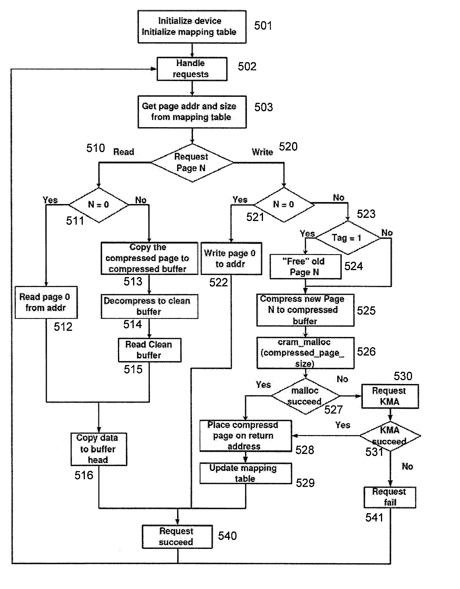
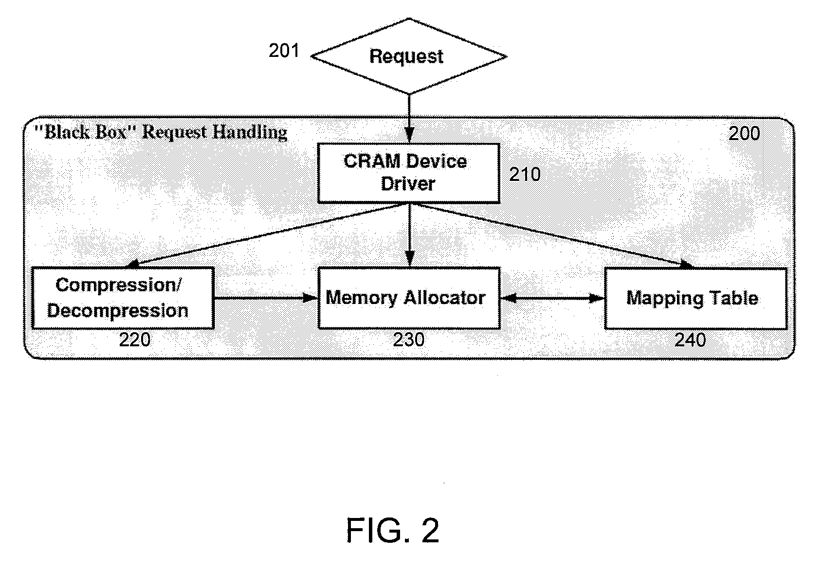
[0005] A dynamic memory compression architecture is disclosed which allows applications with working data sets exceeding the physical memory of an embedded system to still execute correctly. The dynamic memory compression architecture provides “on-the-fly” compression and decompression of the working data in a manner which is transparent to the user and which does not require special-purpose hardware. As memory resource are depleted, pages of data in a main working area of memory are compressed and moved to a compressed area of memory. The compressed area of memory can be dynamically resized as needed: it can remain small when compression is not needed and can grow when the application data grows to significantly exceed the physical memory constraints. In one embodiment, the dynamic memory compression architecture takes advantage of existing swapping mechanisms in the operating system's memory management code to determine which pages of data to compress and when to perform the compression. The compressed area in memory can be implemented by a new block device which acts as a swap area for the virtual memory mechanisms of the operating system. The new block device transparently provides the facilities for compression and for management of the compressed pages in the compressed area of memory to avoid fragmentation.
[0006] The disclosed dynamic memory compression architecture is particularly advantageous in low-power diskless embedded systems. It can be readily adapted for different compression techniques and different operating systems with minimal modifications to memory management code. The disclosed architecture advantageously avoids performance degradation for applications capable of running without compression while gaining the capability to run sets of applications that could not be supported without compression.
[0007] A new compression technique is also herein disclosed which is particularly advantageous when utilized with the above-mentioned dynamic memory compression architecture. Referred to by the inventors as “pattern-based partial match” compression, the technique explores frequent patterns that occur within each word of memory and takes advantage of the similarities among words by keeping a small two-way hashed associated dictionary. The technique can provide good compression ratios while exhibiting low runtime and memory overhead.

Problems solved by technology

Embedded systems, especially mobile devices, have strict constraints on size, weight, and power consumption.
As embedded applications grow increasingly complicated, their working data sets often increase in size, exceeding the original estimates of system memory requirements.

Method used


Image

  • Operating System-Based Memory Compression for Embedded Systems
  • Operating System-Based Memory Compression for Embedded Systems
  • Operating System-Based Memory Compression for Embedded Systems

Examples


Embodiment Construction

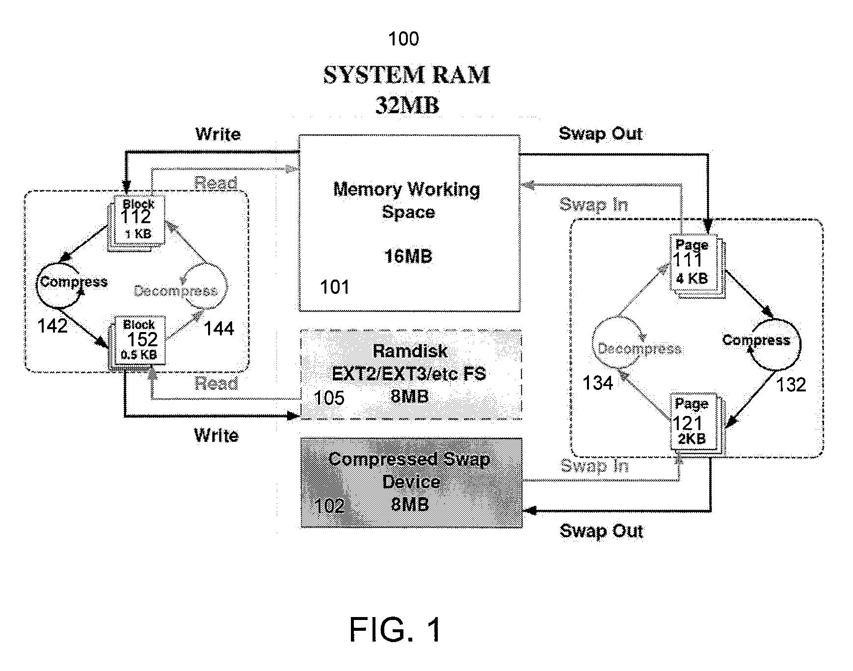
[0016]FIG. 1 is an abstract diagram illustrating the operation of the disclosed memory compression architecture in an example embedded system. The embedded system preferably has a memory management unit (MMU) and is preferably diskless, as further discussed herein.

[0017] As depicted in FIG. 1, the main memory 100 of the embedded system is divided into a portion 101 containing uncompressed data and code pages, referred to herein as the main memory working area, and a portion 102 containing compressed pages. Consider the scenario where the address space of one or more memory intensive processes increases dramatically and exceeds the size of physical memory. A conventional embedded system would have little alternative but to kill the process if it had no hard disk to which it could swap out pages to provide more memory. As further discussed herein, the operating system of the embedded system is modified to dynamically choose some of the pages 111 in the main memory working area 101, c...


PUM


Abstract

A dynamic memory compression architecture is disclosed which allows applications with working data sets exceeding the physical memory of an embedded system to still execute correctly. The dynamic memory compression architecture provides “on-the-fly” compression and decompression of the working data in a manner which is transparent to the user and which does not require special-purpose hardware. A new compression technique is also herein disclosed which is particularly advantageous when utilized with the above-mentioned dynamic memory compression architecture.

Description

[0001] This application claims the benefit of and is a non-provisional of U.S. Provisional Application No. 60 / 696,397, filed on Jul. 1, 2005, entitled “OPERATING SYSTEM-BASED MEMORY COMPRESSION FOR EMBEDDED SYSTEMS,” the contents of which are incorporated by reference herein.STATEMENT REGARDING FEDERALLY SPONSORED R&D [0002] This invention was made in part with support by NSF funding under Grant No. CNS0347942. The U.S. Government may have certain rights in this invention.BACKGROUND OF THE INVENTION [0003] The present invention is related to memory compression architectures for embedded systems. [0004] Embedded systems, especially mobile devices, have strict constraints on size, weight, and power consumption. As embedded applications grow increasingly complicated, their working data sets often increase in size, exceeding the original estimates of system memory requirements. Rather than resorting to a costly redesign of the embedded system's hardware, it would be advantageous to prov...

Claims


Application Information

Patent Timeline
IPC IPC(8): G06F13/00
CPCG06F12/023G06F2212/401G06F12/08
Inventor YANG, LEILEKATSAS, HARISDICK, ROBERTCHAKRADHAR, SRIMAT
Owner NORTHWESTERN UNIV
Learn More