
ePTFE lamination - resizing ePTFE tubing

a technology of eptfe tubing and lamination, which is applied in the field of vascular grafts, can solve the problems of compounding difficulty and normal difficulty in precision

Inactive Publication Date: 2006-12-28
LIFESHIELD SCI
View PDF23 Cites 33 Cited by
  • Summary
  • Abstract
  • Description
  • Claims
  • Application Information

AI Technical Summary

Benefits of technology

[0006] Altering the inner or outer diameter of the vessel structure by adjusting the width of the pleats has significant advantages. First, vessel structures having a relatively few sizes can be fit to a relatively large range of diameters of structural members to create several diameters of vascular grafts.
[0007] A second advantage of adjusting pleat widths to assemble vascular grafts is that the diameter of the inner or liner vessel structure can be formed such that there is minimal clearance required for placing the basis stent or other structural member over it. Then, the outer or cover vessel structure can be placed over the basis stent and pleats formed to bring its diameter into contact with the basis stent. When pressure and heat are applied to the assembly, the vessel structures unite about the basis stent to form the vascular graft.

Problems solved by technology

Such precision is normally difficult, particularly when one or more of the structures is a vessel structure of a vascular graft formed of ePTFE.
Such difficulty is compounded when the ePTFE vessel structure has very small transverse dimensions, such as outer and inner diameters and wall thicknesses.

Method used


Image

  • ePTFE lamination - resizing ePTFE tubing
  • ePTFE lamination - resizing ePTFE tubing
  • ePTFE lamination - resizing ePTFE tubing

Examples


Embodiment Construction

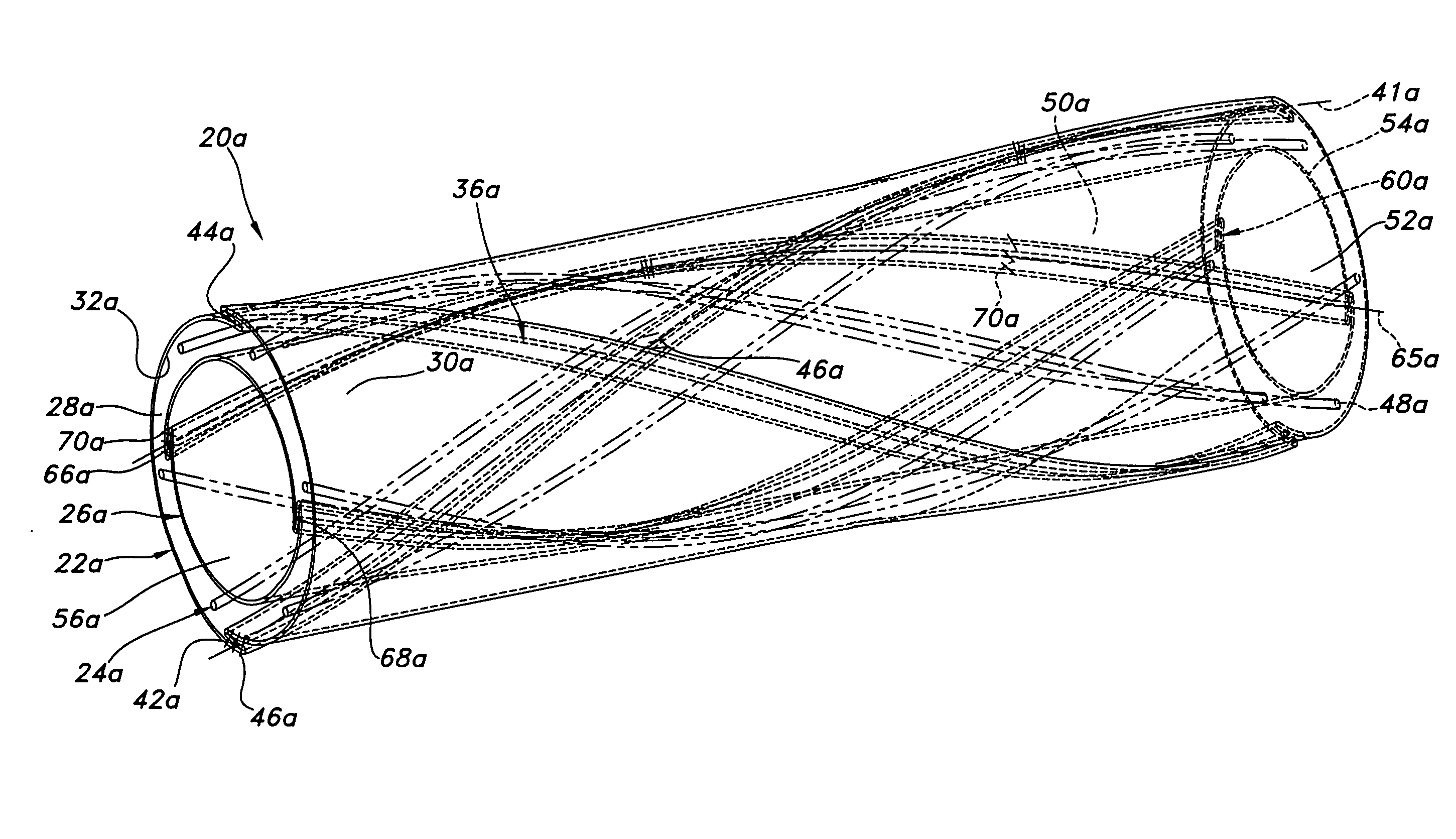
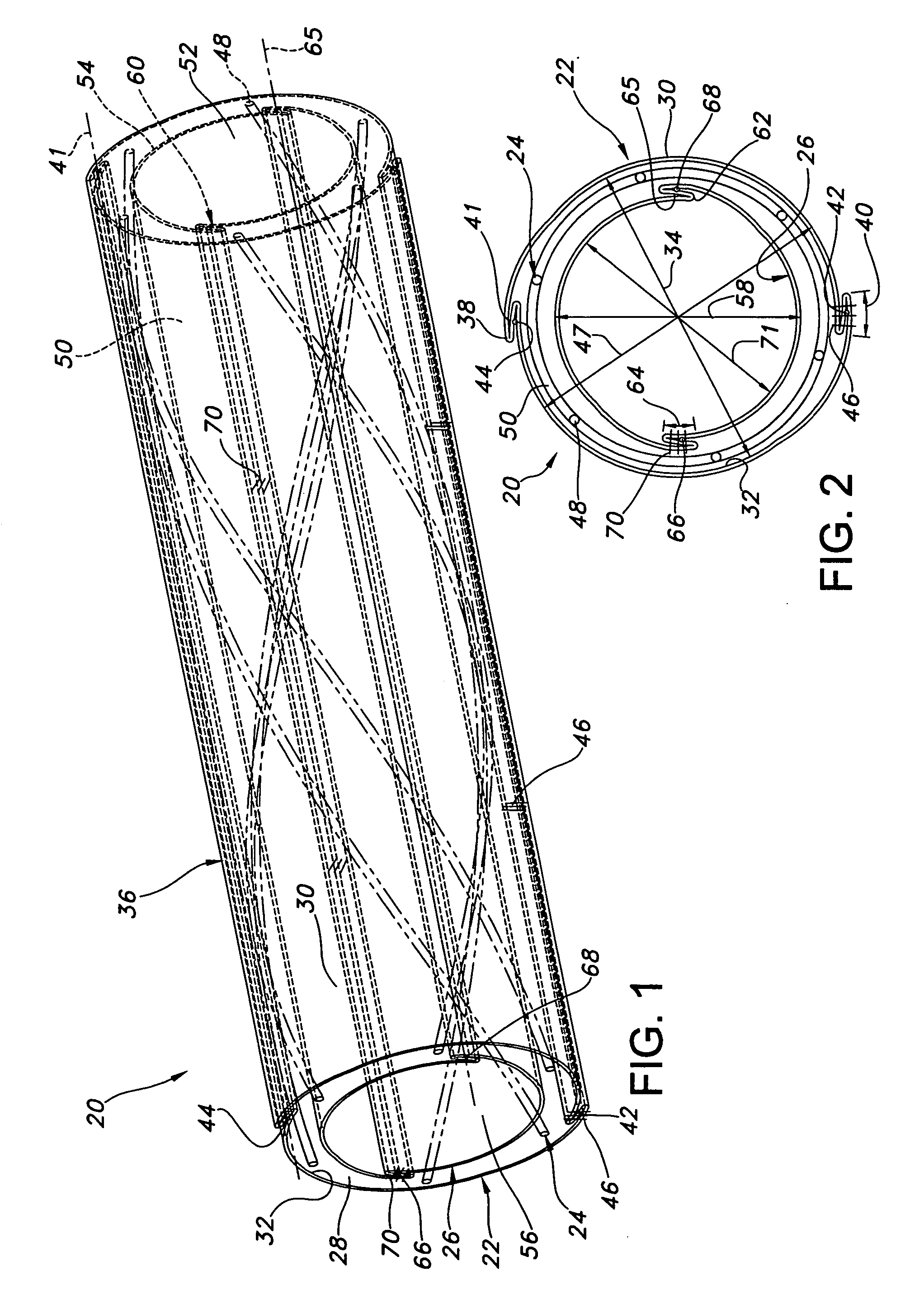
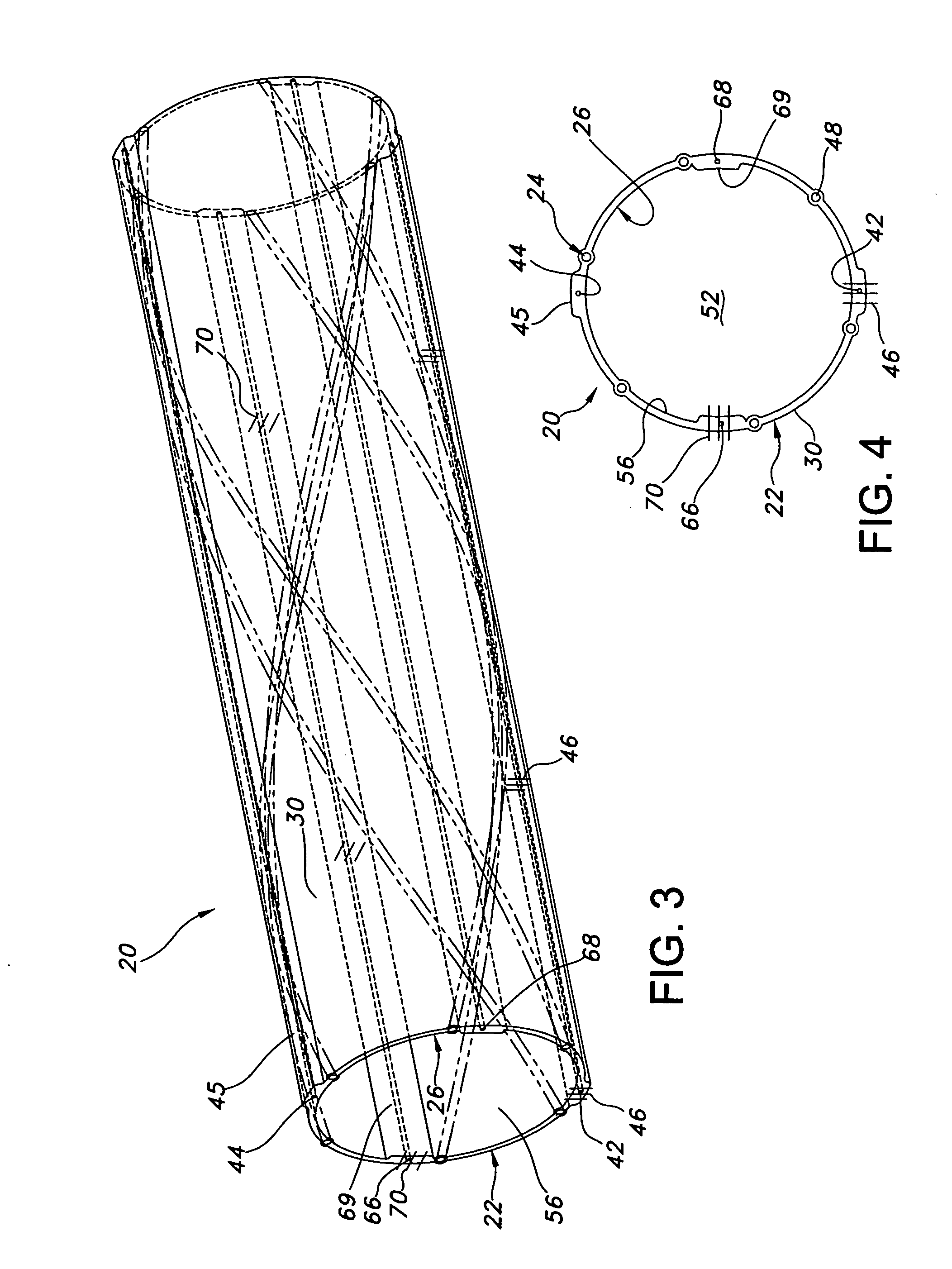
[0025] Referring to the drawings and more particularly to FIGS. 1 and 2, a vascular graft 20 is shown for implantation within a body. The vascular graft 20 includes a cover vessel structure 22, stent structure 24, and liner vessel structure 26. The liner vessel structure 26 is within the stent structure 24 in coaxial relation therewith, and the stent structure 24 is within the cover vessel structure 22 in coaxial relation therewith.

[0026] The cover vessel structure 22 is elongate and has a lumen 28. The cover vessel structure 22 has outer and inner wall surfaces 30, 32 and is formed of expanded polytetrafluoroethylene (ePTFE) material. The cover vessel structure 22 has an annular cross-section which has an inner transverse dimension defined by an inner diameter 34. In alternative embodiments, the cross-section of the cover vessel structure 22 may be non-annular, such as by being rectangular.

[0027] The vascular graft 20 has one or more fold structures 36 which are integral with and...


PUM


Abstract

A vascular graft includes a vessel structure having outer and inner wall surfaces. The vessel structure has outer and inner transverse dimensions. The vascular graft includes a fold structure which is integral with the vessel structure. The fold structure extends from the outer or inner wall surface of the vessel structure for altering the inner or outer transverse dimension thereof. A method for making the vascular graft facilitates formation of the fold structure.

Description

FIELD OF THE INVENTION [0001] The present invention relates to a vascular graft and, more specifically, to a vascular graft having a vessel structure and a pleat structure for varying the size of the vessel structure to fit the size of one or more additional structures, such as a stent, to which the vessel structure is assembled, and to a method for making such a vascular graft. BACKGROUND OF THE INVENTION [0002] It is well known to use extruded tube structures of polytetrafluoroethylene (PTFE) as implantable intraluminal prostheses, particularly for the vessel structures of vascular grafts. PTFE is particularly suitable as an implantable prosthesis as it exhibits superior biocompatibility. PTFE tube structures may be used for the vessel structures of vascular grafts in the replacement, repair of or supplement to a blood vessel as PTFE exhibits excellent mechanical properties and low thrombogenicity. In vascular applications, the vessel structures are manufactured from expanded poly...

Claims


Application Information

Patent Timeline
IPC IPC(8): A61F2/06A61F2/88
CPCA61F2/06A61F2/07Y10T156/1051A61F2250/001A61F2002/072
Inventor PECKHAM, JOHNMUSBACH, FRANK A.
Owner LIFESHIELD SCI
Learn More