Latch for a hitch mountable load carrier

Inactive Publication Date: 2006-12-28
THULE SWEDEN AB
View PDF27 Cites 7 Cited by
  • Summary
  • Abstract
  • Description
  • Claims
  • Application Information

AI Technical Summary

Benefits of technology

[0007] The present invention incorporates several features that minimize and / or alleviate the disadvantages outlined above. In particular, problems of misalignment between the support arm and extending arm of a swing-away vehicular load carrier may be reduced or eliminated according to the present invention using a rotary latch movable between an engaged position and a released position. Operation of the rotary latch requires a rotating rod that extends away from the rotary latch for remote operation to provide added safety and prevent injury by inadvertent insertion of an operator's fingers or hands in the gripping portion of the latching mechanism.
[0012] At the end of a journey, to move the carrier structure away from the rear of the vehicle or for more convenient access to articles attached to the load carrier, a sequence of steps converts the vehicle mountable load carrier from the locked position to the extended position of the extending arm, wherein the hinge of the load carrier is in its open position. One example of a load carrier according to the present invention may be opened by unlocking the handle attached to the rod opposite the curved latch that secures the extending arm, also referred to herein as the second beam. Once freed, turning the handle causes the rod to rotate, whereby the curved latch retracts from around the projection of to the first beam. The length of the rod provides suitable separation of the handle from the curved latch to prevent operator injury when the latch releases the projection, allowing the extending arm to rotate about the hinge and away from the first beam. Rotation of the extending arm away from the first beam provides space between the rear of the vehicle and articles attached to the extending arm. Maximum vehicle clearance and access to articles occurs when the extending arm has been rotated to its extended position.

Problems solved by technology

Weights of such magnitude place a significant strain on the hinge of the load carrier.

Method used


Image

  • Latch for a hitch mountable load carrier
  • Latch for a hitch mountable load carrier
  • Latch for a hitch mountable load carrier

Examples


Embodiment Construction

[0026] As required, detailed embodiments of the present invention are disclosed herein; however, it is to be understood that the disclosed embodiments are merely exemplary of the invention that may be embodied in various and alternative forms. The figures are not necessarily to scale; some features may be exaggerated or minimized to show details of particular components. Therefore, specific structural and functional details disclosed herein are not to be interpreted as limiting, but merely as a basis for the claims and as a representative basis for teaching one skilled in the art to variously employ the present invention.

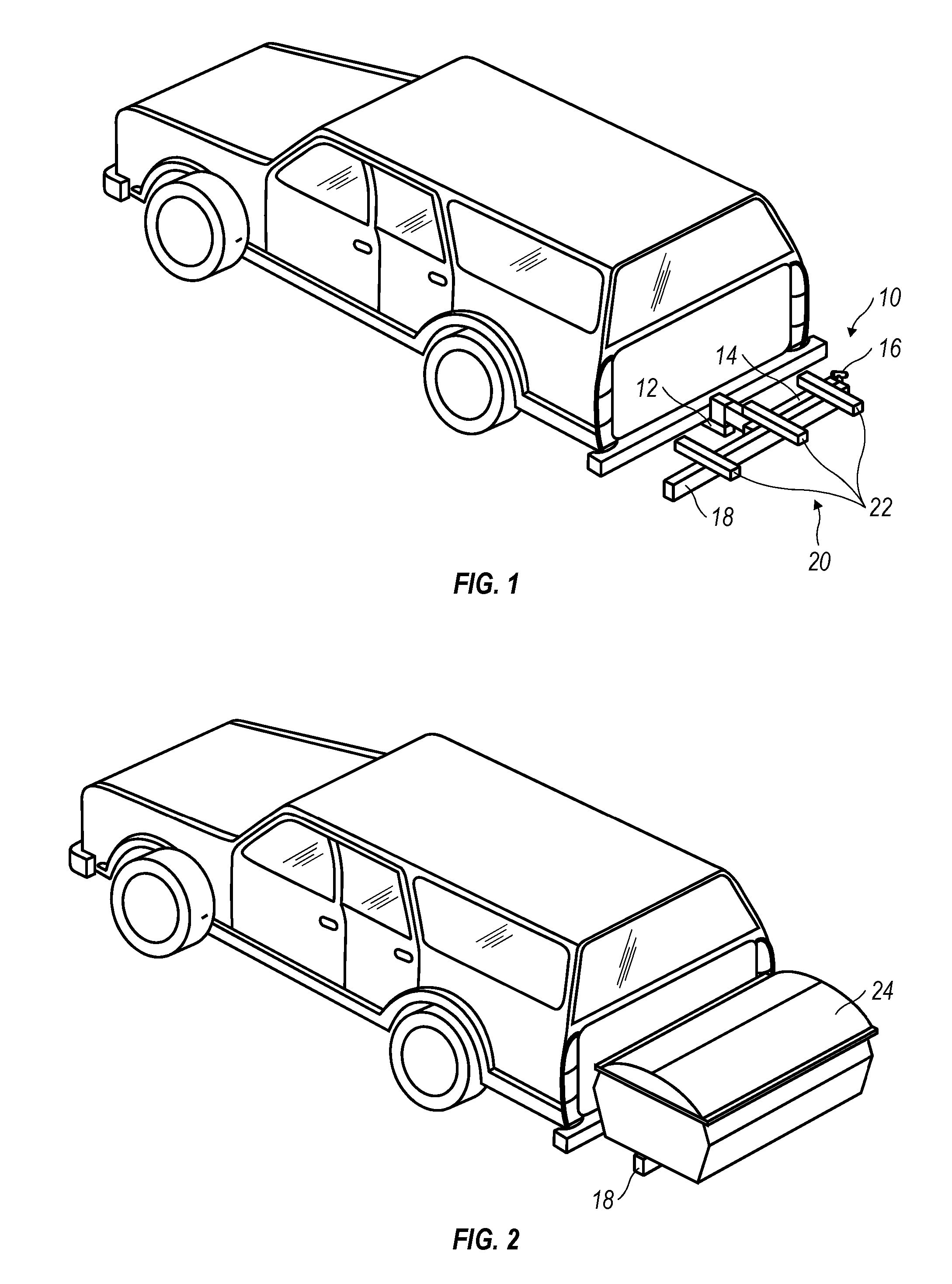
[0027] Referring now to the figures wherein like reference numerals identify like parts throughout the several views, FIG. 1 shows a load carrier 10 according to the present invention used for supporting articles, such as storage containers, at the rear of a transporting vehicle. The load carrier 10 includes a stinger 12, inserted in the receiving hitch of the tran...


PUM


Abstract

A vehicular load carrier including a hinge having an open position and a closed position. The load carrier includes a first beam having a first end attached to the hinge, and a second end deploying a projection. A second beam is attached to the hinge for rotation relative to the first beam. The second beam has an edge for mounting a rotatable rod having a handle opposite a curved latch. Upon rotation of the handle, between a first position and a second position, the curved latch moves from a released position to a position where it engages the projection to hold the first beam and the second beam together when the hinge is in its closed position.

Description

CROSS-REFERENCE TO RELATED APPLICATIONS [0001] The present application claims the benefit of U.S. Provisional Application No. 60 / 689,158 filed Jun. 10, 2005. Said application is expressly incorporated herein by reference in its entirety.FIELD OF THE INVENTION [0002] The present invention relates generally to articles including modular-type carrier assemblies mounted upon a transporting vehicle. An exemplary embodiment utilized herein for illustrative purposes is a hitch-mounted vehicular load carrier designed for supporting a variety of articles including storage containers. A disclosed assembly includes a hinged, swing-away frame that provides convenient access for loading and unloading one or more articles, which may be transported by the load carrier. BACKGROUND OF THE INVENTION [0003] Attachment of load carriers at rearward positions of vehicles, using hitch-mount receivers, is known. Rear-mounted load carriers typically provide transportation for sports equipment particularly b...

Claims


Application Information

Patent Timeline
IPC IPC(8): H01R13/627
CPCB60R9/065
Inventor BOGOSLOFSKI, KEVINFORTUNE, WILLIAMNIEDZIELA, THEODORE
Owner THULE SWEDEN AB
Why Eureka
Try Eureka