
Digital camera

a digital camera and camera body technology, applied in the field of digital cameras, can solve the problems of imager damage, and the slr camera with live view capability is more likely to damage the imager

Active Publication Date: 2006-12-28
OM DIGITAL SOLUTIONS CORP
View PDF4 Cites 18 Cited by
  • Summary
  • Abstract
  • Description
  • Claims
  • Application Information

AI Technical Summary

Benefits of technology

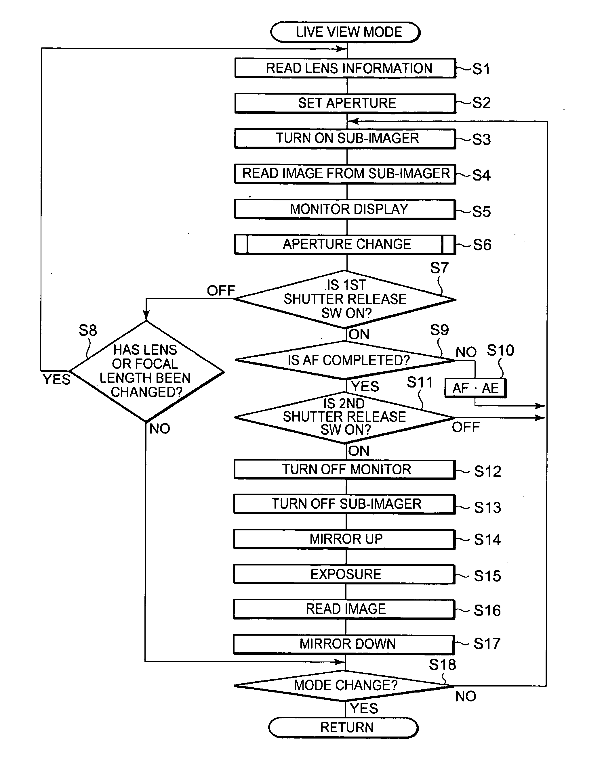
[0009] Since the aperture mechanism is controlled based on the photographing lens-specific information in a live-view initialization process, the possibility of damaging an imager while a photographer is framing a picture can be reduced.
[0013] According to the present invention, there can be provided a digital camera, especially a single-lens reflex camera capable of displaying a live view, which is much less likely to damage its imager during framing.

Problems solved by technology

In this case, if the sun is included in a frame, it could cause damage to an imager.
Especially, an SLR camera with live view capability is more likely to damage its imager because the imager continues to be exposed during framing.

Method used


Image

  • Digital camera
  • Digital camera
  • Digital camera

Examples


first embodiment

[0026] (First Embodiment)

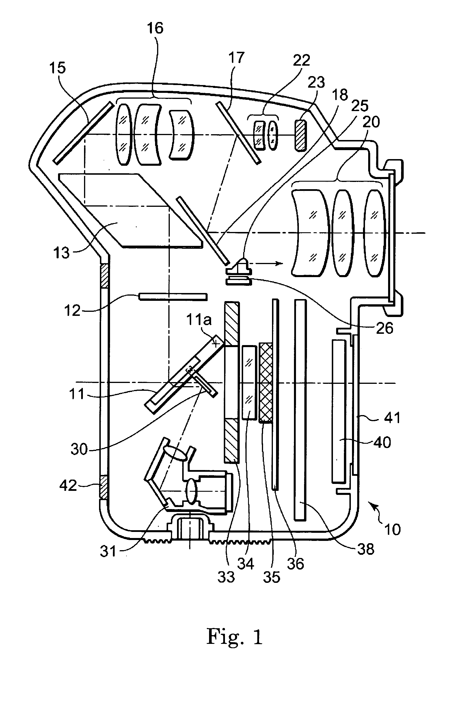
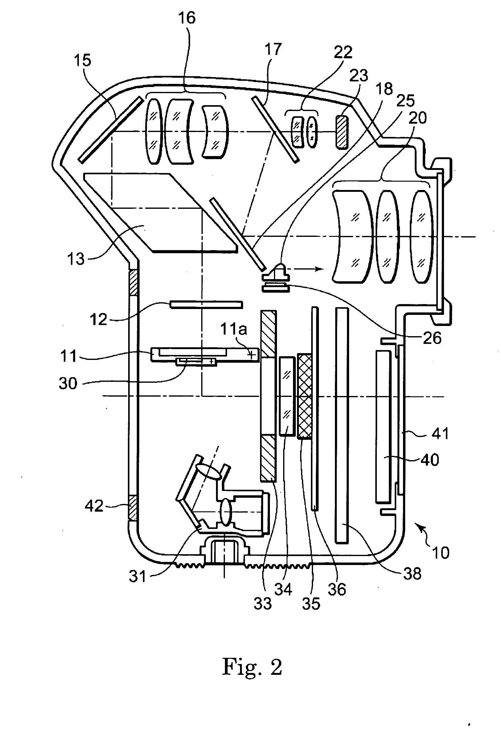
[0027]FIGS. 1 and 2 are sectional views showing the structure of the body section of a single-lens reflex digital camera according to a first embodiment of the present invention. FIG. 1 shows the camera state during viewing of a subject field, and FIG. 2 shows the camera state upon shooting. Further, FIG. 3 is a sectional view showing the structure of an interchangeable lens of the single-lens reflex digital camera according to the embodiment.

[0028] In FIGS. 1 and 2, this single-lens reflex digital camera (hereinafter simply called the “camera”) consists principally of a camera body 10 as a camera body section and an interchangeable lens 80 shown in FIG. 3. Any desired interchangeable lens 80 can be removably set on a body mount 42 provided on the front of the camera body 10.

[0029] In FIG. 1, a light beam coming from a subject through the interchangeable lens 80 (not shown) is reflected on the surface of a main mirror 11, part of which is formed into a hal...

second embodiment

[0075] (Second Embodiment)

[0076] The following describes a second embodiment of the present invention.

[0077] In the first embodiment, a live view is displayed using the sub-imager provided in the finder optical system, while in the second embodiment, a live view is displayed through the main imager without using the sub-imager.

[0078] In the second embodiment, a camera body 10′ has the same structure as the camera body 10 in the first embodiment, except that an AF / AE optical system and an AF / AE sensor are arranged in the position of the sub-imager in the first embodiment, and that the position of the focusing screen is different from that in the first embodiment. There is no change in the interchangeable lens from that in the first embodiment shown in FIG. 3. Therefore, portions common to those in the first embodiment are given the same reference numerals and their repetitive description will be omitted. In other words, only the portions different from those in the first embodiment...


PUM


Abstract

The present invention discloses a digital camera having a live view mode for continuously capturing and displaying a series of subject images, in which when the live view mode is selected, a computation part initializes an aperture mechanism based on photographing lens-specific information. Since the aperture mechanism is controlled based on the photographing lens-specific information in a live-view initialization process, the possibility of damaging an imager while a photographer is framing a picture can be reduced. The photographing lens-specific information includes, for example, focal length information and maximum aperture value information. The computation part can be configured, for example, to initialize the aperture mechanism in such a manner that the amount of light from the sun per unit area, or the total amount of light from the sun, will always become almost equal regardless of the kind of photographing lens.

Description

CROSS-REFERENCE TO RELATED APPLICATION [0001] This application is based upon and claims the benefit of priority from prior Japanese Patent Application No. 2005-186714, filed Jun. 27, 2005, the entire contents of which are incorporated herein by reference. BACKGROUND OF THE INVENTION [0002] 1. Field of the Invention [0003] The present invention relates to a digital camera, and more particularly, to the improvement of a single-lens reflex digital camera capable of displaying on a display screen both an image being viewed and an image being shot. [0004] 2. Description of the Related Art [0005] Cameras are commonly known, which form an optical image of a subject on an image pickup device from light coming from the subject and passing through a photographing optical system, photoelectrically convert the optical image into electric image signals through the image pickup device, and display the resulting image on the screen of an image display device, such as an LCD monitor, based on the e...

Claims


Application Information

Patent Timeline
Patent Type & Authority Applications(United States)
IPC IPC(8): G03B7/095H04N23/75
CPCG03B7/095G03B7/20H04N5/235H04N5/23209G03B19/12H04N23/663H04N23/70
Inventor TERADA, HIROSHI
Owner OM DIGITAL SOLUTIONS CORP
Learn More