Information processing system, information processing apparatus, and information processing method
- Summary
- Abstract
- Description
- Claims
- Application Information
AI Technical Summary
Benefits of technology
Problems solved by technology
Method used
Image
Examples
first embodiment
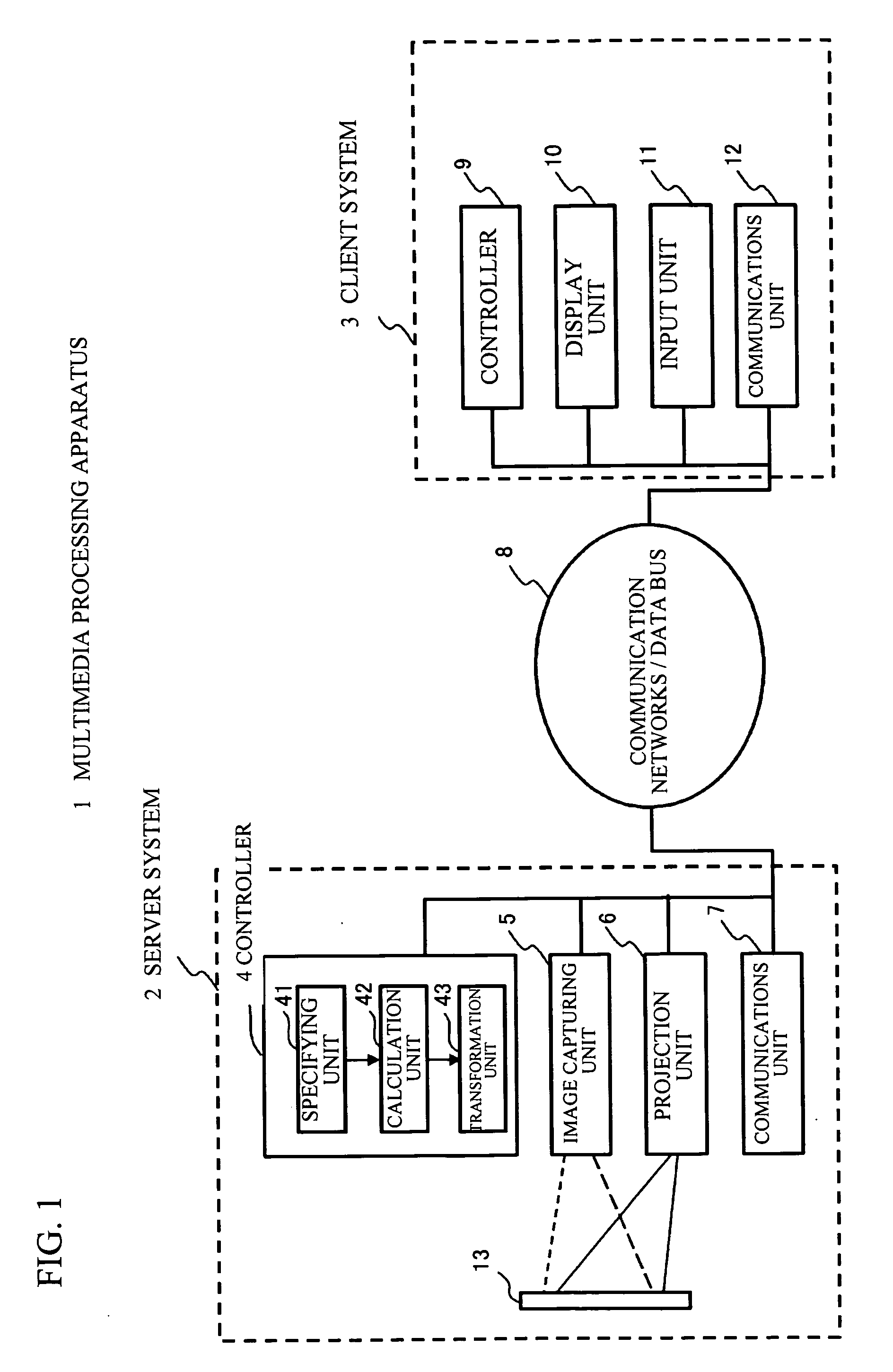
[0044]FIG. 1 schematically shows a functional configuration of a multimedia apparatus 1 in accordance with an embodiment of the present invention. Referring to FIG. 1, the multimedia apparatus (information processing system) 1 is composed a server system 2 and a client system 3. The server system 2 includes a controller (information processing device) 4, an image data capturing unit 5, a projection unit 6, and a communications unit 7; a transmitter device and a receiver device. The client system 3 includes a controller 9, a display unit 10, an input unit 11, and a communications unit 12. The server system 2 and the client system 3 are connected to each other via communication networks or a data bus 8.
[0045] The controller 4, the image data capturing unit 5, the projection unit 6, and the communications unit 7 are connected to one another via internal networks, data line, control line, or the like provided in the server system 2. In the same manner, the controller 9, the display uni...
second embodiment
[0093] A description will now be given of a second embodiment of the present invention. In the first embodiment, the description has been given of a case where a shape of rectangle is employed for the image data for calibration. In the second embodiment, another image data for calibration will be exemplified. FIGS. 10A and 10B are views showing other examples of the image data for calibration. FIG. 10A shows image data for calibration 241 formed of four identical squares. FIG. 10B shows image data for calibration 242 formed of a hexagon having six triangles. The projection unit 6 projects the image data for calibration 241 formed of four identical squares and the image data for calibration 242 formed of a hexagon having six triangles, with the infrared lights. The image data capturing unit 5 captures the projection image data. The specifying unit 41 on the controller 4 specifies the points to be calibrated of the image data for calibration with the projection unit 6. The calculation...
third embodiment
[0095] A description will be given of a third embodiment of the present invention. In the third embodiment, a color wheel is employed for an optical system. FIG. 12 is a view showing a projection unit 106, in which the projection unit 6 includes a color wheel. The projection unit 106 projects the image data for calibration and the projection image data in an identical optical system, whereas the image data for calibration is projected with the infrared lights and the projection image data is projected with the visible lights.
[0096] Specifically, as shown in FIG. 12, the projection unit 106 includes the visible light band data processing circuit 61, the infrared ray band data processing circuit 63, a color wheel 107, a DMD (Digital Micro mirror Device) 108, a light source 109, lenses for combination circuit 110 and 111, and a lens 112. FIG. 11 is a view showing an example of the color wheel 107. As shown in FIG. 11, the color wheel 107 is composed of a filter that corresponds to a r...
PUM
 Abstract
Description
Claims
Application Information
 - R&D
- Intellectual Property
- Life Sciences
- Materials
- Tech Scout
- Unparalleled Data Quality
- Higher Quality Content
- 60% Fewer Hallucinations
Browse by: Latest US Patents, China's latest patents, Technical Efficacy Thesaurus, Application Domain, Technology Topic, Popular Technical Reports.
© 2025 PatSnap. All rights reserved.Legal|Privacy policy|Modern Slavery Act Transparency Statement|Sitemap|About US| Contact US: help@patsnap.com


