
Maximum power point motor control

a power point motor and maximum power technology, applied in the direction of electric variable regulation, process and machine control, instruments, etc., can solve the problems of damage to the motor, difficult to meet the power requirements of the load, and difficult to efficiently operate the ac pump from a solar array

Inactive Publication Date: 2006-12-28
WORLDWATER & SOLAR TECH
View PDF9 Cites 129 Cited by
  • Summary
  • Abstract
  • Description
  • Claims
  • Application Information

AI Technical Summary

Benefits of technology

"The invention is a method and apparatus for controlling the speed of an AC motor in a DC source - inverter - AC motor system. The inverter or motor drive is controlled by software to track the maximum power available from the DC source by sensing the voltage of the DC source and adjusting the frequency of the AC output to match the available power. This allows the motor to operate at its optimum speed for any given voltage. The technical effect of the invention is to improve the efficiency and performance of AC motors in DC source systems."

Problems solved by technology

However, because of changes in both the source and the load, it can be difficult to meet the power requirements of the load.
Thus it can be difficult to efficiently operate an AC pump from a solar array.
However, if the motor continues to run at the same speed, e.g. 60 Hz, then as the voltage drops, the current must increase to meet the power requirements, until the increased current can damage the motor.
Thus, controlling motors at fixed frequency is very difficult.
However, it is difficult to track power.

Method used


Image

  • Maximum power point motor control
  • Maximum power point motor control
  • Maximum power point motor control

Examples


Embodiment Construction

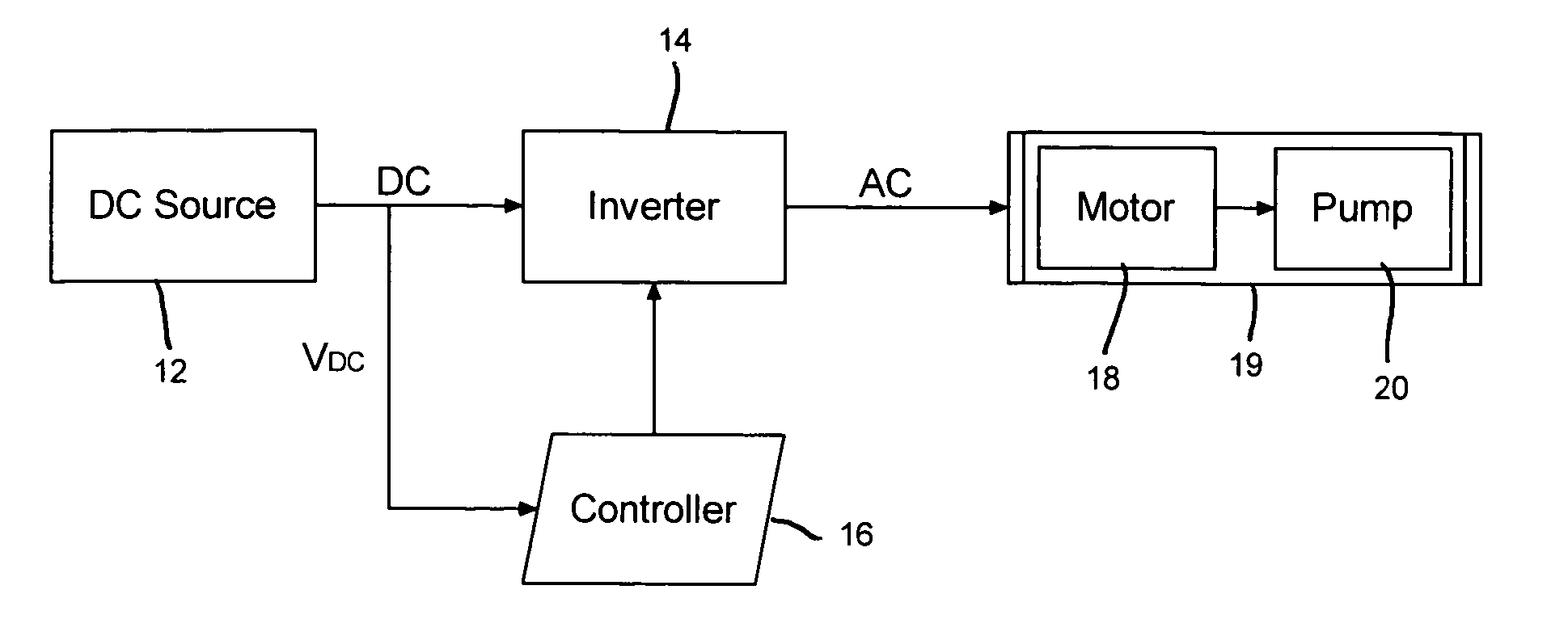
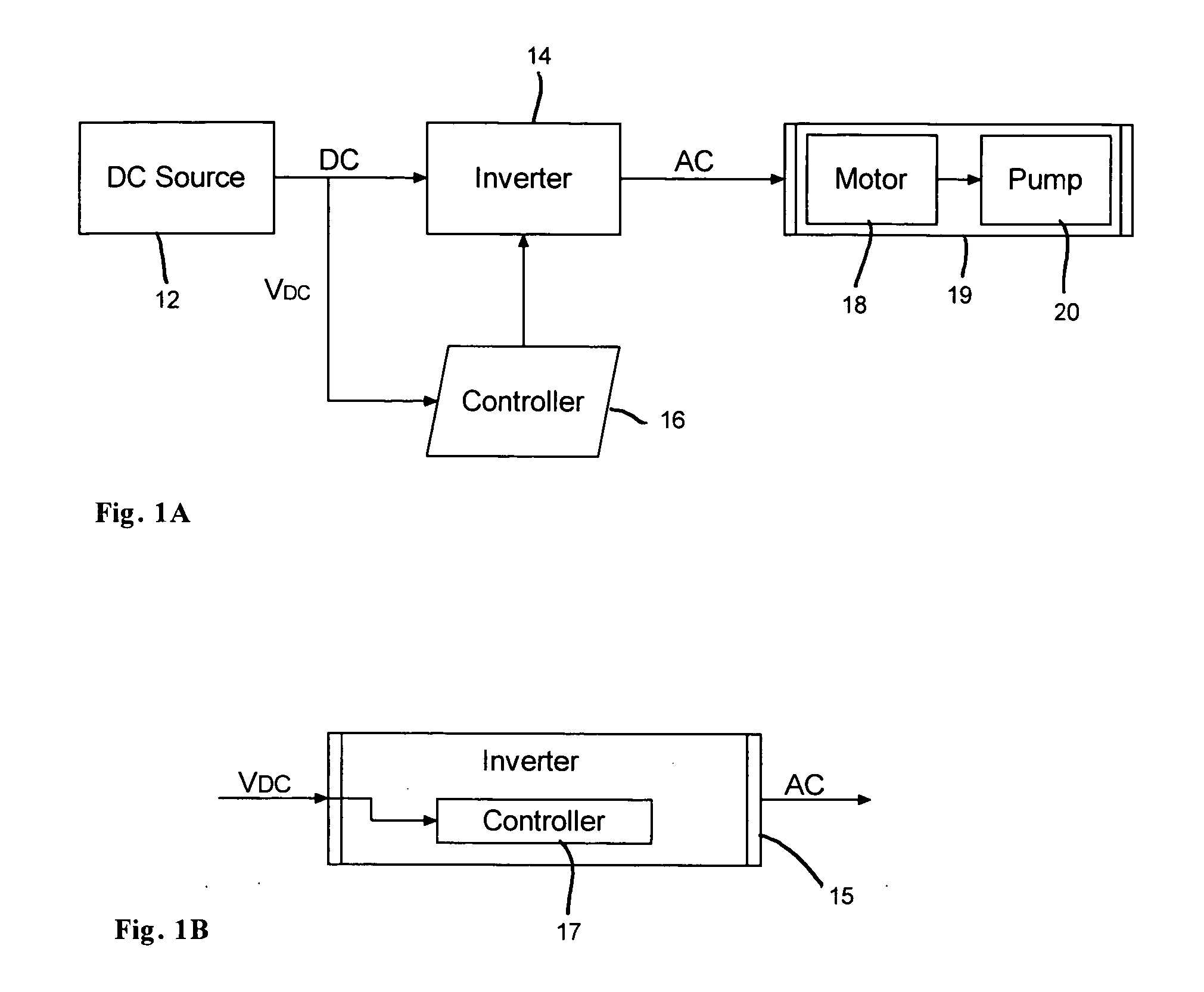
[0025] As shown in FIG. 1A, a DC source—software controlled inverter—AC motor system 10 according to the invention comprises a DC source 12, an inverter 14 connected to the DC source 12, a programmed controller 16 connected to the inverter 14, and an AC motor 18 connected to the inverter 14. DC source 12 is preferably a solar array made up of conventional silicon solar cells or panels, but may be another type of DC source. The DC source will generally be a source whose output voltage and power vary. The AC motor is typically a three phase motor, and may drive a water pump 20 (or other device), which may be combined with motor 18 into a single integral unit 19. The invention may also be applied to other loads that have load characteristics similar to motor 18.

[0026] Inverter 14 is a conventional DC to AC converter, also commonly known as a motor drive or variable speed drive (VFD). Controller 16 is programmed to carry out an algorithm which produces maximum power point tracking by v...


PUM


Abstract

A method and apparatus are implemented in software to control motor speed as a function of available power in a DC sourceinverterAC motor system, i.e. to perform maximum power tracking of motor speed. An inverter or motor drive converts DC power from a DC source, such as a solar panel, to AC power, to power the motor. The inverter or motor drive is controlled by software, implemented either by programmable features built directly into the inverter or drive or by a separate programmable device connected to the inverter or drive, to track motor power as a function of source power. The software-controlled inverter or drive sets motor speed as a function of source power by sensing only a single parameter, the DC source voltage. The software-controlled inverter or drive samples the source voltage at preset intervals, and changes the frequency of the AC output of the inverter or drive to match or track the available power so that the motor operates at or near its optimum for any source voltage.

Description

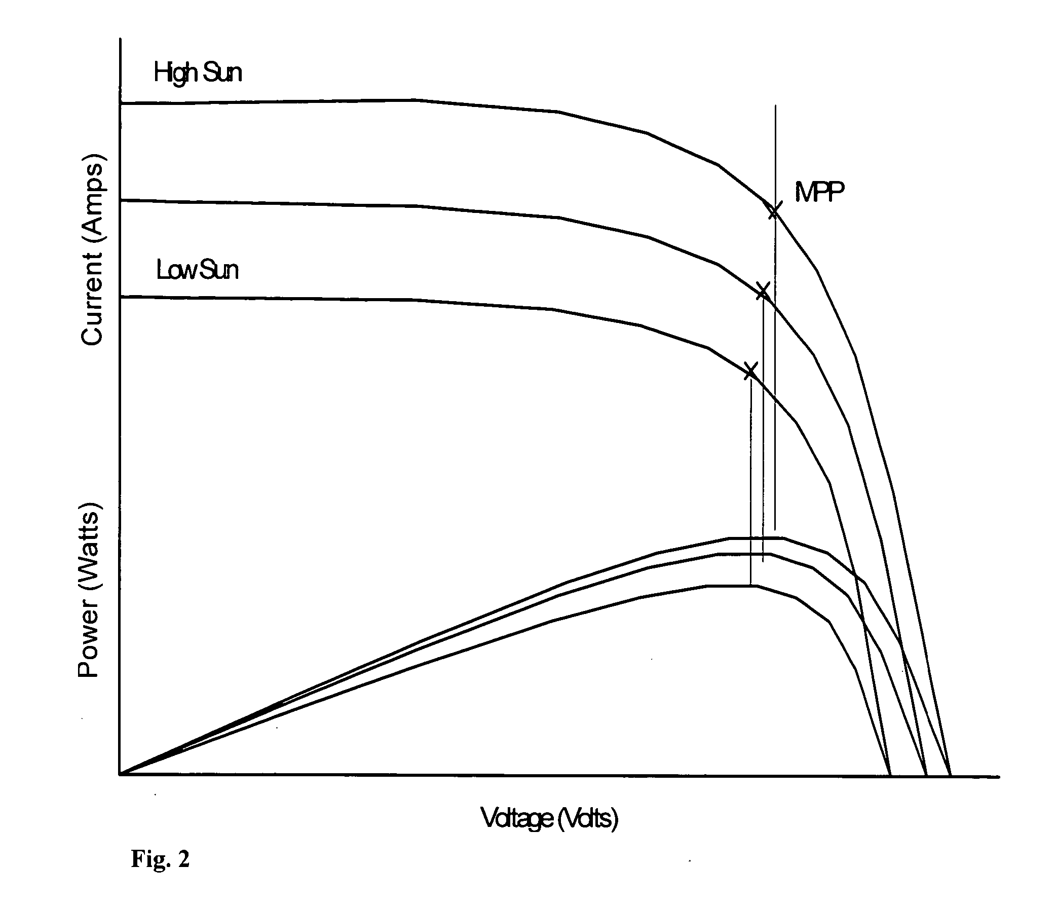
BACKGROUND OF THE INVENTION [0001] 1. Field of the Invention [0002] The present invention relates generally to the operation of AC motors or similar loads with AC motor drives that convert power from a DC source to AC, and more particularly to operation of the motor at maximum power as the power from the-DC source varies. A particular application is to solar powered systems and to water pumps. [0003] 2. Description of Related Art [0004] An AC load can be powered from a DC source by using a converter to change DC to AC. However, because of changes in both the source and the load, it can be difficult to meet the power requirements of the load. For example, a photovoltaic solar cell array is a DC source. However, the current-voltage (I-V) curve shifts under varying conditions, e.g. amount of sun. Thus the available power will vary. One application of solar power is to operate water pumps, which typically include three phase AC motors. However, the load curve of the AC pump motor can al...

Claims


Application Information

Patent Timeline
Patent Type & Authority Applications(United States)
IPC IPC(8): H02P7/42
CPCH01L31/02021H02J7/35Y10S323/906Y02E10/58H02P23/0077Y02E10/56
Inventor MCNULTY, THOMAS CHARLESHORTA, JUAN CARLOSPLAISIME, JOACINE
Owner WORLDWATER & SOLAR TECH
Learn More