Image forming device and detachably loaded process unit

a technology of image forming device and process unit, which is applied in the direction of electrographic process apparatus, instruments, optics, etc., can solve the problems of inability to reduce the cost the image forming device cannot be structurally simplified, and the size of the image forming device cannot be reduced, so as to achieve easy loading or unloading, easy mounting and dismounting, and easy disassembly and installation

Inactive Publication Date: 2006-12-21
BROTHER KOGYO KK
View PDF2 Cites 30 Cited by
  • Summary
  • Abstract
  • Description
  • Claims
  • Application Information

AI Technical Summary

Benefits of technology

[0010] Another object of the invention is to provide a process unit in which a developing unit can be easily mounted on and dismounted from a photosensitive unit.
[0039] The developing unit is pivotally movable about the second guide shaft when both end portions of the second guide shaft are located in the second terminals. Accordingly, the developing unit can be easily mounted on and dismounted from the photosensitive unit by grasping the rear end of the developing unit, orienting the second guide shaft downward, and moving the second guide shaft along the guide grooves formed in the photosensitive unit. In this case, the photosensitive unit may be accommodated in the photosensitive unit accommodating section or may be unloaded from the image forming device and placed outside the image forming device.

Problems solved by technology

However, the image forming device cannot be structurally simplified and made compact in size and also the cost of the image forming device cannot be lowered if the rigid locking mechanism is employed.

Method used


Image

  • Image forming device and detachably loaded process unit
  • Image forming device and detachably loaded process unit
  • Image forming device and detachably loaded process unit

Examples


Embodiment Construction

[0062] A laser beam printer according to a preferred embodiment of the invention will be described with reference to the accompanying drawings. In the following description, the terms “downward”, “front”, “rear”, “above”, “below”, “beneath” and the like will be used assuming that the laser beam printer is disposed in an orientation in which it is intended to be used.

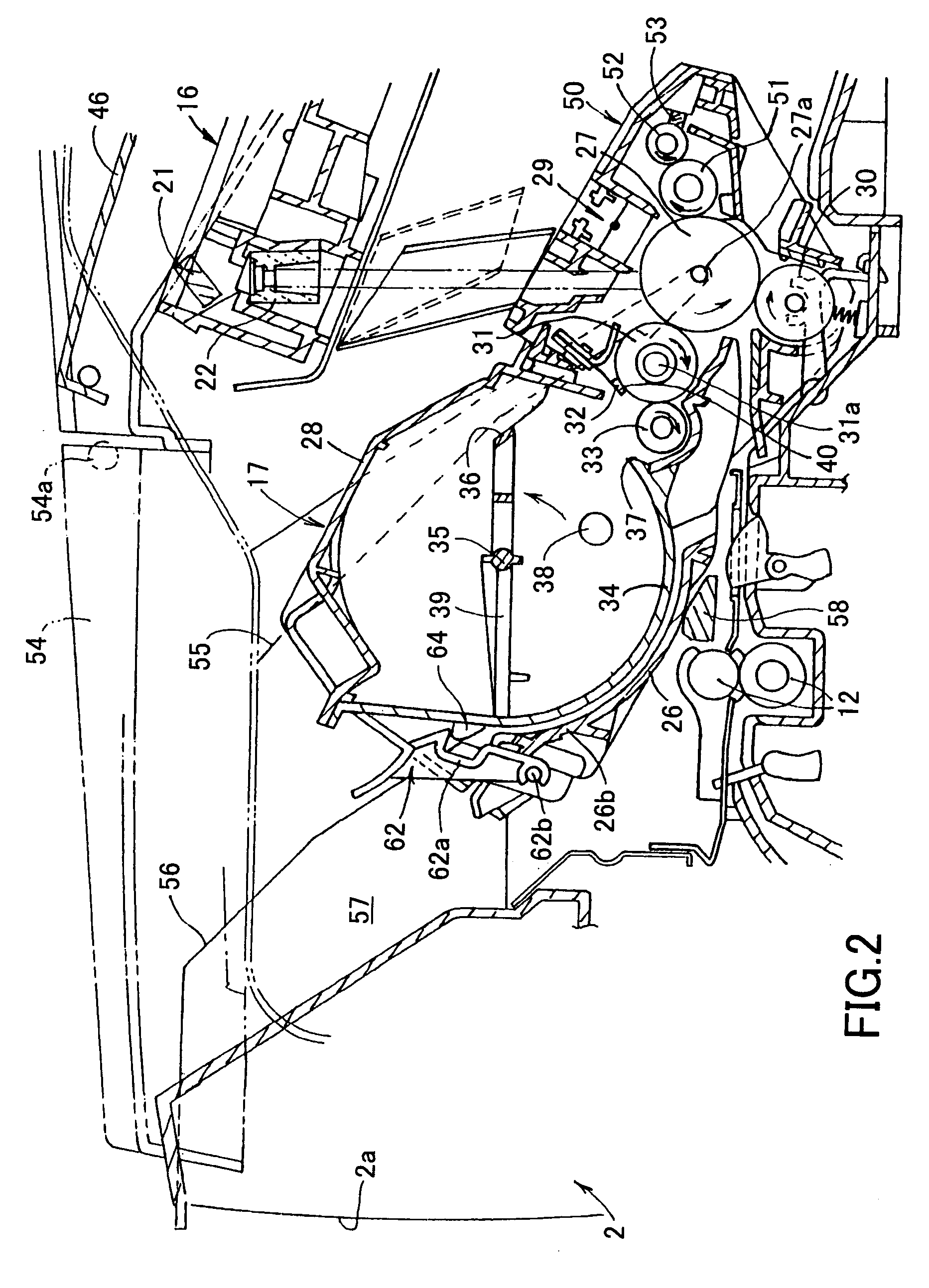
[0063]FIG. 1 is a cross-sectional view showing the laser beam printer. As shown in this figure, the laser beam printer 1 has a housing 2 in which a sheet feed section 4 and an image forming section 5 are disposed. The image forming section 5 forms images on paper sheets supplied by the sheet feed section 4.

[0064] The sheet feed section 4 includes a sheet feed tray 6, a sheet urging plate 7, a sheet feed roller 8, a sheet feed pad 9, a pair of paper dust removing rollers 10, a pair of sheet feed rollers 11, and a pair of registration rollers 12. The sheet feed tray 6 is detachably provided on the bottom portion of the h...


PUM


Abstract

A developing unit is detachably mounted on a photosensitive unit to form a combined unit called process unit. In use, the process unit is loaded into an electrophotographic image forming device. A rotational shaft of the photosensitive drum projects out from the photosensitive unit. When the process unit is loaded into the image forming device from a top open space, both ends of the rotational shaft are engaged with a pair of guides formed in side walls of the image forming device and guided down along the guides. The process unit is accommodated in an accommodating section when both ends of the rotational shaft have brought into abutment with stops at the ends of the guides and a trailing end of the process unit is rotated downward about the rotational shaft.

Description

[0001] This is a Division of application Ser. No. 10 / 851,233 filed May 24, 2004, which is a Division of application Ser. No. 10 / 242,953 filed Sep. 13, 2002, which claims foreign priority from the following Japanese Patent Applications: JP 2001-277604 filed Sep. 13, 2001, JP 2001-277605 filed Sep. 13, 2001, JP 2001-277606 filed Sep. 13, 2001, JP 2002-7656 filed Mar. 25, 2002 and JP 2002-7657 filed Mar. 25, 2002. The entire disclosures of the prior applications are hereby incorporated by reference herein in their entirety.BACKGROUND OF THE INVENTION [0002] 1. Field of the Invention [0003] The present invention relates to an electrophotographic image forming device, such as a laser beam printer, a copying machine, or a facsimile device. More particularly, the invention relates to a process unit detachably loaded into the image forming device and a structure of the image forming device for receiving and accommodating the process unit. [0004] 2. Description of the Related Art [0005] Conv...

Claims


Application Information

Patent Timeline
Patent Type & Authority Applications(United States)
IPC IPC(8): G03G21/18G03G15/04G03G15/08
CPCG03G15/0896G03G21/1853G03G21/1864G03G2221/1884G03G2221/163G03G2221/1853G03G2221/1606
Inventor OKABE, YASUSHI
Owner BROTHER KOGYO KK
Why Eureka
Try Eureka