
Fundus photography apparatus

a technology of photography apparatus and lens, applied in the field offundus photography apparatus, can solve the problems of complex automatic exposure mechanism and poor setting, and achieve the effects of reducing the task, simplifying the adjustment of the exposure value, and preventing overexposur

Inactive Publication Date: 2006-12-21
KOWA CO LTD
View PDF2 Cites 16 Cited by
  • Summary
  • Abstract
  • Description
  • Claims
  • Application Information

AI Technical Summary

Benefits of technology

[0011] In this invention, the spectral distribution of the iris in the anterior ocular segment of the eye is detected from the image thereof, and the detection results are used as a basis for adjusting the exposure value during photography of the eye fundus. This can prevent overexposure such as in the case of blue eyes, for example, and alleviates the task of correcting the photographic exposure value for different iris colors.
[0012] Moreover, the image of the anterior ocular segment can be obtained during alignment prior to photographing the eye fundus, simplifying the adjustment of the exposure value.

Problems solved by technology

However, such an automatic exposure mechanism is so complex that generally an optimum reference exposure is set based on the photography conditions, pupil diameter, or past experience of the examiner and he or she corrects the set exposure for eye fundus photography.
However, people's eyes are infinitely varied, and the above exposure setting may not provide the best results.

Method used


Image

  • Fundus photography apparatus
  • Fundus photography apparatus
  • Fundus photography apparatus

Examples


Embodiment Construction

[0019] The embodiment of the invention will now be described with reference to the accompanying drawings.

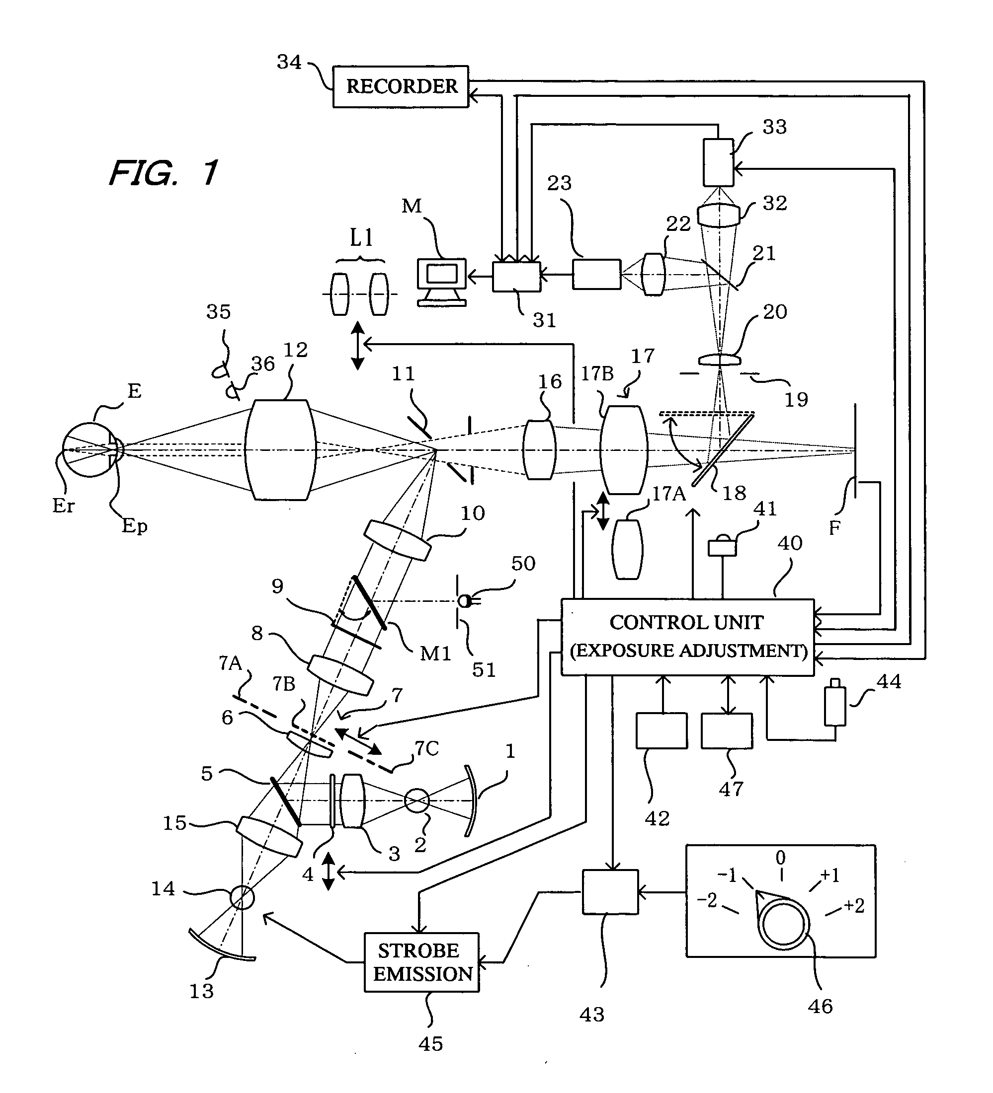
[0020]FIG. 1 shows the configuration of the principal parts that include the optical system of the fundus photography apparatus of the invention. In FIG. 1, an observation light source 2 such as a halogen lamp or the like is located at the focus of a mirror 1. Light from the light source 2 passes via a condenser lens 3, a visible-light cutting and infrared transmitting filter 4, a mirror 5, a lens 6, and impinges on a ring-slit 7 that shapes the light into a ring-shaped beam. The mirror 5 may be a half-mirror, a dichroic mirror (that transmits visible light and reflects infrared light), or a return mirror (retractable mirror). The ring-slit 7 comprises a ring-slit 7A for mydriatic photography, a ring-slit 7B for non-mydriatic photography, and a small-pupil ring-slit 7C, any one of which can be inserted into the optical path depending on the photography mode being used and the ey...


PUM


Abstract

A fundus photography apparatus is provided that enables optimal adjustment of exposure values according to the color characteristics of the anterior ocular segment of the subject eye. The fundus photography apparatus comprises means for photographing the anterior ocular segment of the eye, means for photographing the eye fundus, and means for detecting the spectral distribution of the iris of the eye based on images of the anterior ocular segment. The photographic exposure value is adjusted in preparation for fudus photography based on the detected spectral distribution of the iris.

Description

BACKGROUND OF THE INVENTION [0001] 1. Field of the Invention [0002] The present invention relates to a fundus photography apparatus, particularly to an eye fundus photography apparatus equipped with means for photographing the anterior ocular segment of the eye and means for photographing the eye fundus illuminated with a beam of light. [0003] 2. Description of the Prior Art [0004] In order for a fundus photography apparatus to obtain good-quality images of the eye fundus, the fundus has to be illuminated with light of optimal intensity during the photography. Doing this requires an automatic exposure mechanism to detect the intensity of light reflected from the fundus and set the exposure accordingly. However, such an automatic exposure mechanism is so complex that generally an optimum reference exposure is set based on the photography conditions, pupil diameter, or past experience of the examiner and he or she corrects the set exposure for eye fundus photography. [0005] When, for ...

Claims


Application Information

Patent Timeline
Patent Type & Authority Applications(United States)
IPC IPC(8): A61B3/14
CPCA61B3/12
Inventor MATSUMURA, KAZUNORI
Owner KOWA CO LTD
Learn More