
Electric fishing reel

a technology of electric reels and reels, which is applied in the field of electric fishing reels, can solve the problems of difficult to reduce the size of the entire electric reel, easy to make meshing noises (chatter), and difficult to reduce the size of the electric reel, so as to reduce the space necessary especially in the rotational axial direction, reduce the size, and reduce the effect of nois

Inactive Publication Date: 2006-12-21
DAIWA SEIKO CORPORATION
View PDF6 Cites 4 Cited by
  • Summary
  • Abstract
  • Description
  • Claims
  • Application Information

AI Technical Summary

Benefits of technology

[0006] The present invention has been conceived on the basis of the problems thus far described, and has an object to provide an electric fishing reel which is provided with a speed change mechanism excellent in silence and durability while realizing the size reduction.

Problems solved by technology

This arrangement raises a problem that the additional spaces are needed in the radial directions thereby to make it difficult to reduce a size of the entire electric reel.
Especially in the electric reel of the arrangement, in which the drive motor and the reduction gear mechanism are arranged in the spool, the size reduction of the electric reel is made more difficult by the relation between the size of the spool and the line winding capacity.
This transmission raises a problem that meshing noises (chatter) are easily made by the gears rotating at the high speed at the time of power transmission.
Therefore, these gears are subject to useless loads for endurance although they are not used for the power transmission, which is not preferable.

Method used


Image

  • Electric fishing reel
  • Electric fishing reel
  • Electric fishing reel

Examples


first embodiment

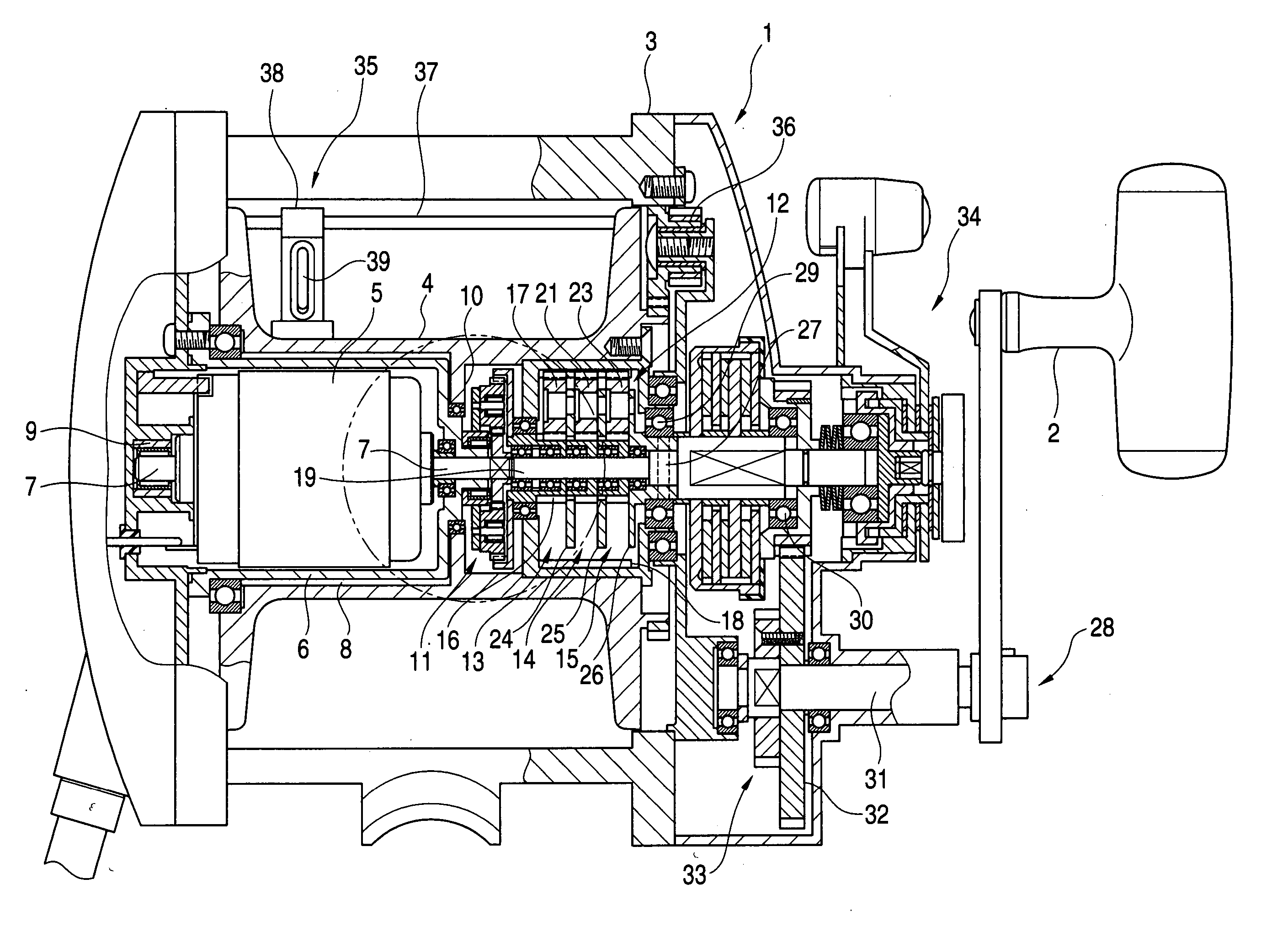
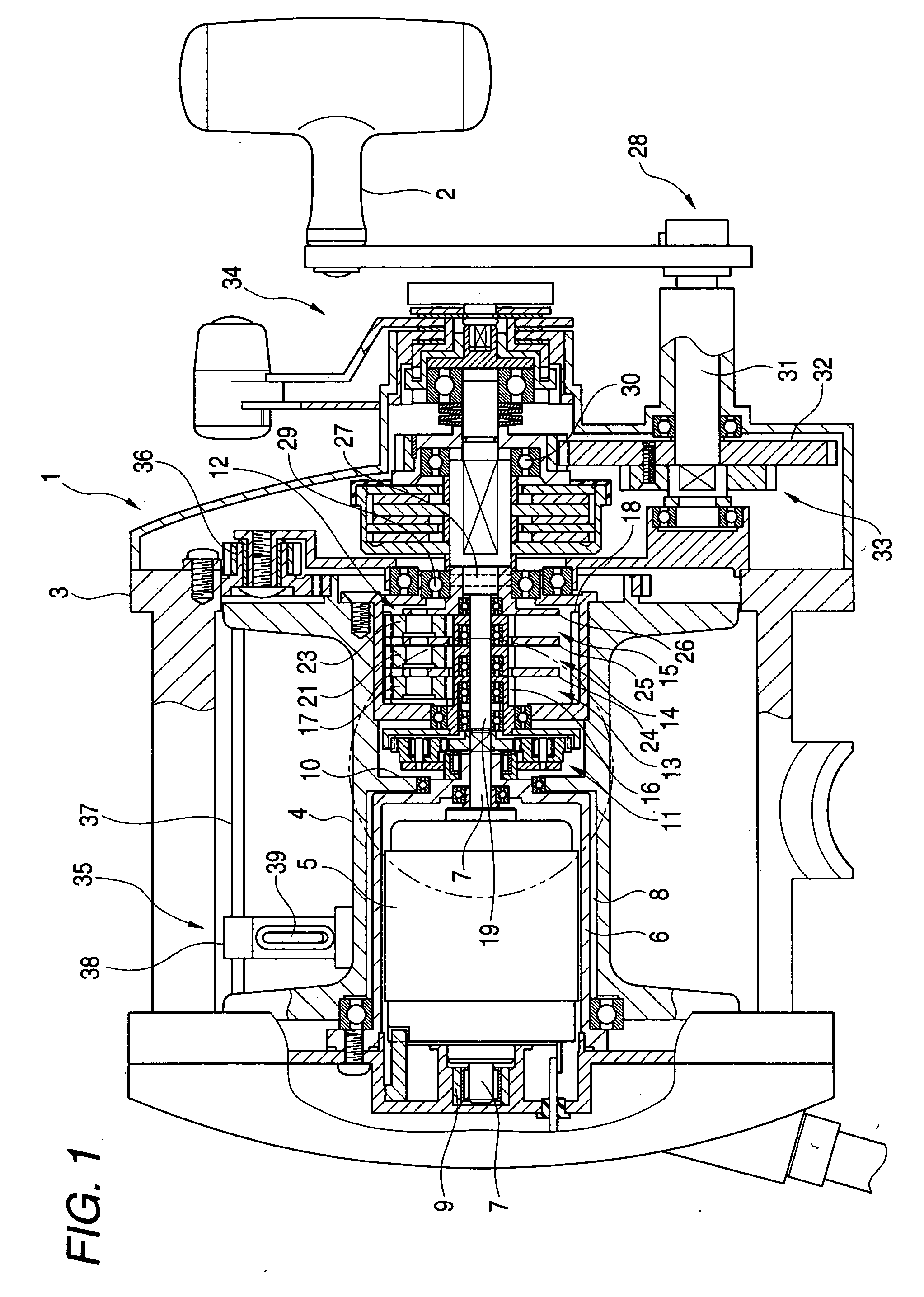
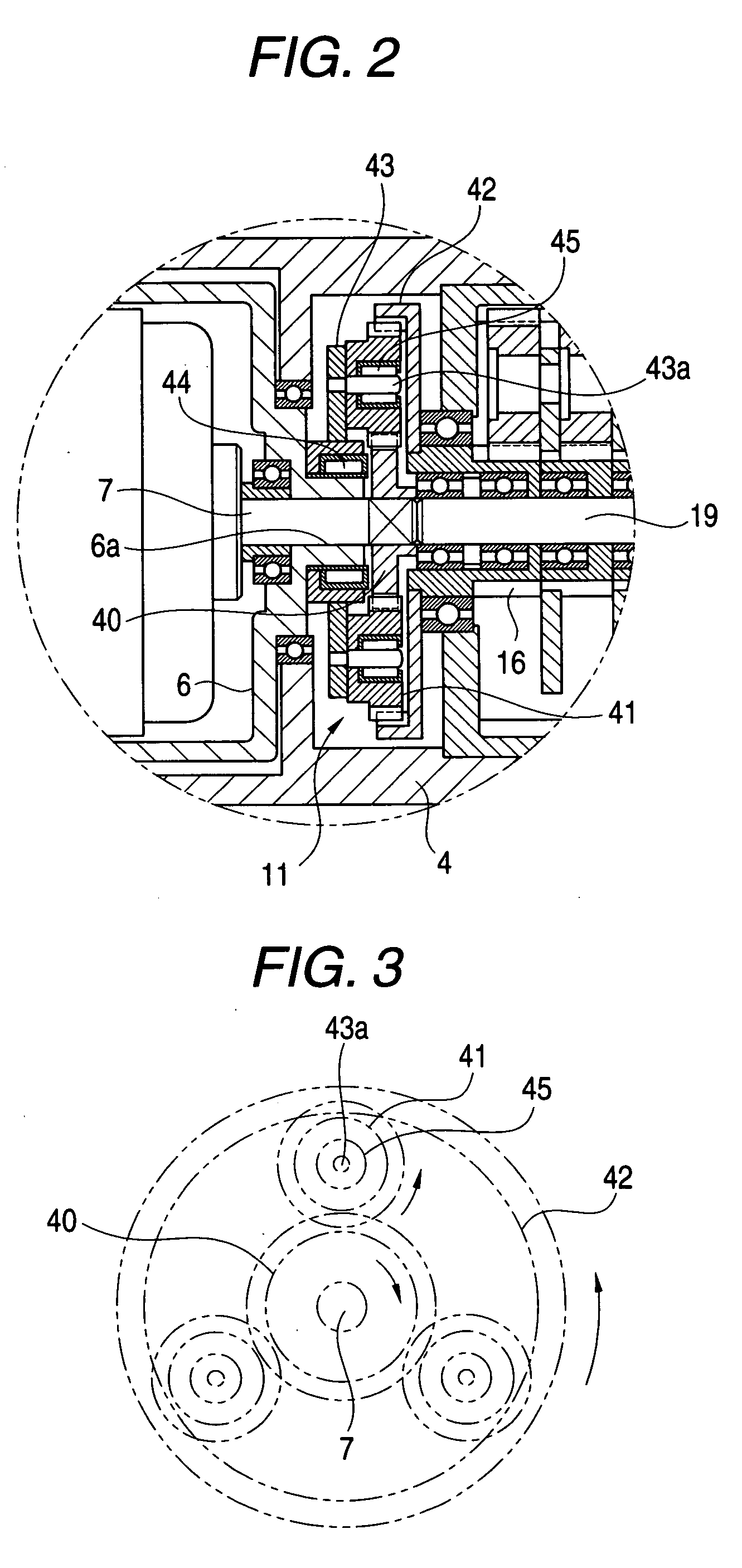
[0038]FIG. 1 to FIG. 4 show a first embodiment of the electric fishing reel according to the invention. FIG. 1 is a partially sectional top plan view showing a portion, in which a speed change mechanism is arranged. FIG. 2 is a diagram showing the construction of the speed change mechanism. FIG. 3 is a schematic diagram for explaining a power transmission route in a low-speed mode. FIG. 4 is a schematic diagram for explaining a power transmission route in a high-speed mode. Here, the “forward rotation” means a clockwise rotation, as viewed in FIG. 1 from the left side side, and the “backward rotation” means a counter-clockwise rotation, as viewed in the same as above.

[0039] An electric fishing reel 1 of this embodiment is equipped with a reel body 3, to which a manual handle 2 is attached. Between the left side and right side frames constructing the reel body 3, a spool 4 is rotatably supported through a bearing. In this spool 4, there is held a drive motor 5, which can be switched...

second embodiment

[0068] A second embodiment of the invention will be described with reference to FIG. 5 to FIG. 8. FIG. 5 is a partially sectional view showing a portion in which the speed change mechanism is arranged; FIG. 6 is a diagram showing a construction of the speed change mechanism; FIG. 7 is a schematic diagram for explaining a power transmission route in a high-speed mode; and FIG. 8 is a schematic diagram for explaining a power transmission route in a low-speed mode. In the embodiment to be described in the following, the components similar to those of the aforementioned first embodiment are designated by the common reference numerals, and their detailed description is omitted. Here, the “forward rotation” means a clockwise rotation, as viewed in FIG. 5 from the right side side, and the “backward rotation” means a counter-clockwise rotation, as viewed in the same direction as above.

[0069] In the second embodiment, a spool shaft 46 is rotatably supported through a bearing between the lef...


PUM


Abstract

An electric fishing reel which is provided with a speed change mechanism excellent in silence and durability while realizing the size reduction. The electric fishing reel comprises: a drive motor for rotationally driving a spool rotatably supported on a reel body; a speed change mechanism rotatably mounted on a motor spindle and including an output gear having a rotational speed switched into a high speed or a low speed in accordance with the rotational direction of the motor spindle; and a power transmission mechanism for transmitting the rotation of the output gear to the spool. The speed change mechanism switches the rotational speed of the output gear by regulating the transmission of the rotation of the motor spindle with respect to the output gear.

Description

BACKGROUND OF THE INVENTION [0001] The present invention relates to an electric fishing reel which is provided with a drive motor for rotationally driving a spool rotatably supported on a reel body. [0002] Generally, the electric fishing reel is provided with a speed change mechanism for reeling operations at a speed according to the situations. As this speed change mechanism, there has been proposed (as referred to Japanese Patent No. 3,537,363, for example) a mechanical type speed change mechanism, in which a high-speed reduction gear mechanism and a low-speed reduction gear mechanism are connected between a motor output shaft and a spool power transmission mechanism so that the power transmission state is switched into the high speed and the low speed by selecting one gear mechanism in accordance with the rotational direction of a drive motor. [0003] In the mechanical type speed change mechanism disclosed in Japanese Patent No. 3,537,363, however, the high-speed and low-speed pow...

Claims


Application Information

Patent Timeline
Patent Type & Authority Applications(United States)
IPC IPC(8): A01K89/017
CPCA01K89/017
Inventor ONO, MASASHI
Owner DAIWA SEIKO CORPORATION
Learn More