
Hinge for a vehicle door

Inactive Publication Date: 2011-03-22
EDSCHA AG
View PDF23 Cites 11 Cited by
  • Summary
  • Abstract
  • Description
  • Claims
  • Application Information

AI Technical Summary

Benefits of technology

[0005]The adjusting arrangement according to the invention for adjusting the end stop makes it possible for the end stop for limiting the opening movement of the two hinge parts to be adjustable, as a result of which different opening angles of the vehicle door are provided. It is thus possible for the hinge to be able to be matched to different vehicle doors which have different opening angles such that the hinge with an adjusting arrangement according to the invention for the end stop can be used in any type of vehicle door. The arrangement of the adjusting arrangement on one of the two hinge parts provides a compact constructional form of the hinge and reduces the construction space necessary for the adjusting arrangement. In addition, hinges which are already being used can therefore be retrofitted in a simple manner with the adjusting arrangement.
[0006]Furthermore, generally at least two hinges are arranged on a vehicle door, with the forces which occur in the end stop essentially being absorbed by one of the two hinges, and the end stop of the other of the two hinges merely being used as an emergency end stop, for example if the first hinge end stop should fail. In this case, the end stops of the two hinge parts are aligned with respect to each other in such a manner that the first hinge firstly strikes against its end stop, with the first hinge in the process absorbing all of the forces which occur and are produced by the striking of the vehicle door. The adjusting arrangement for adjusting the end stop makes it possible to adjust the end stop of the first hinge and the end stop of the second hinge with respect to each other such that, when the vehicle door strikes, the two hinges strike simultaneously against the end stop, and the forces which occur during the striking of the door are distributed to both hinge parts. The forces which occur during the striking of the door in the end stop are compensated for by a correspondingly solid configuration of the hinges. By distributing the forces to both hinges, a corresponding, weight-reduced configuration of the two hinges is provided.
[0010]The engagement element is expediently prestressed against the toothing by a spring element such that the engagement element can be securely fixed in the toothing, and the end stop is securely fixed. This avoids the end stop being displaced by external influences, for example by opening of the vehicle door, and therefore no longer being appropriately adjusted.
[0011]The toothing is advantageously provided in curved form, with the curvature expediently being designed as an arc of a circle, the center point of which is provided on the hinge axis. The effect achieved by this is that the adjustment of the end stop is in parallel with the pivoting movement of the hinge, and therefore the adjustment of the end stop takes place with the opening movement of the vehicle door in a common pivoting movement. By this means, extensive adjustment of the opening angle of the hinge is avoided.

Problems solved by technology

A disadvantage of this type of hinge is the fact that the opening angle of the hinge is predetermined by the end stop.

Method used


Image

  • Hinge for a vehicle door
  • Hinge for a vehicle door
  • Hinge for a vehicle door

Examples


Embodiment Construction

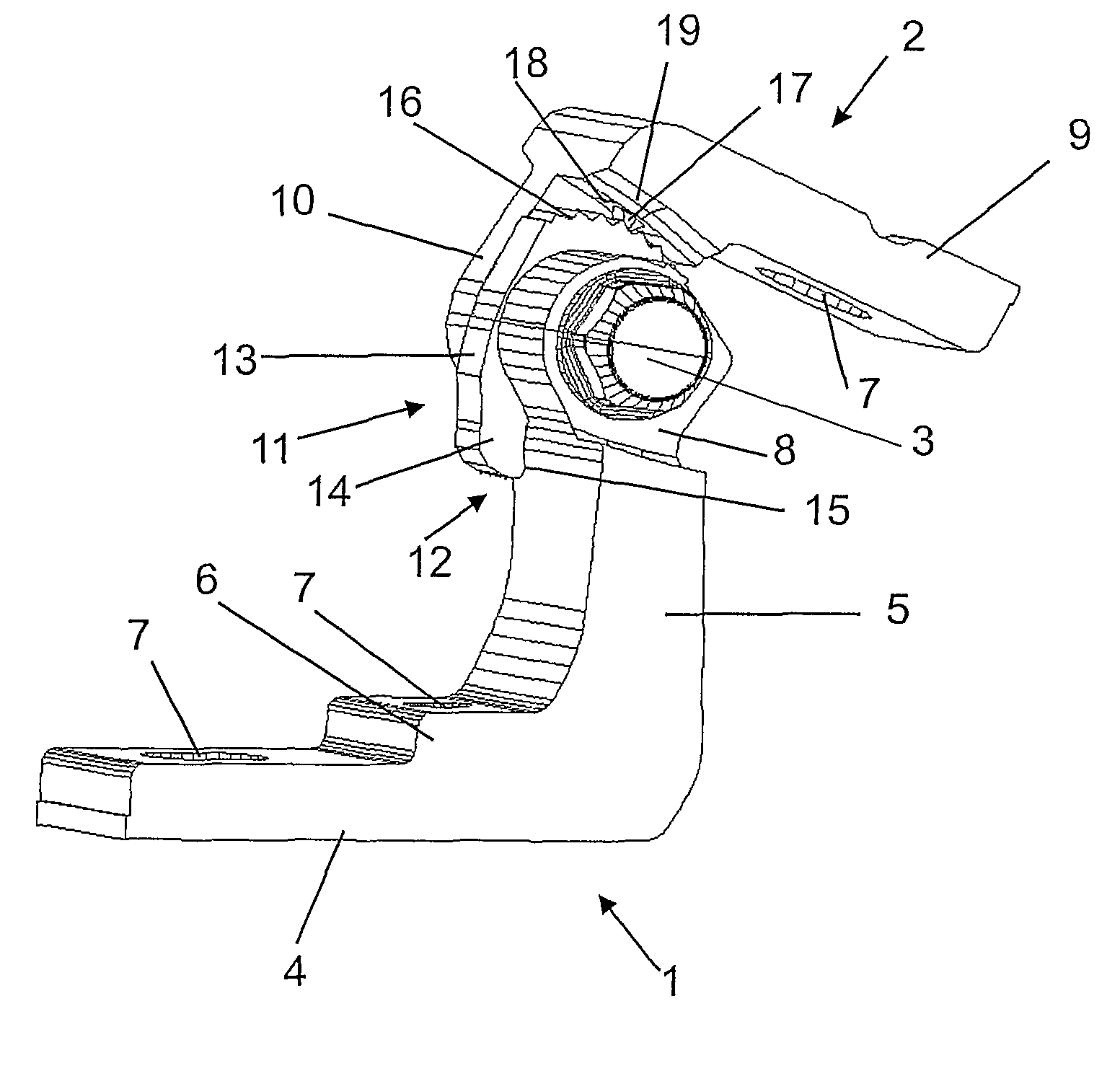
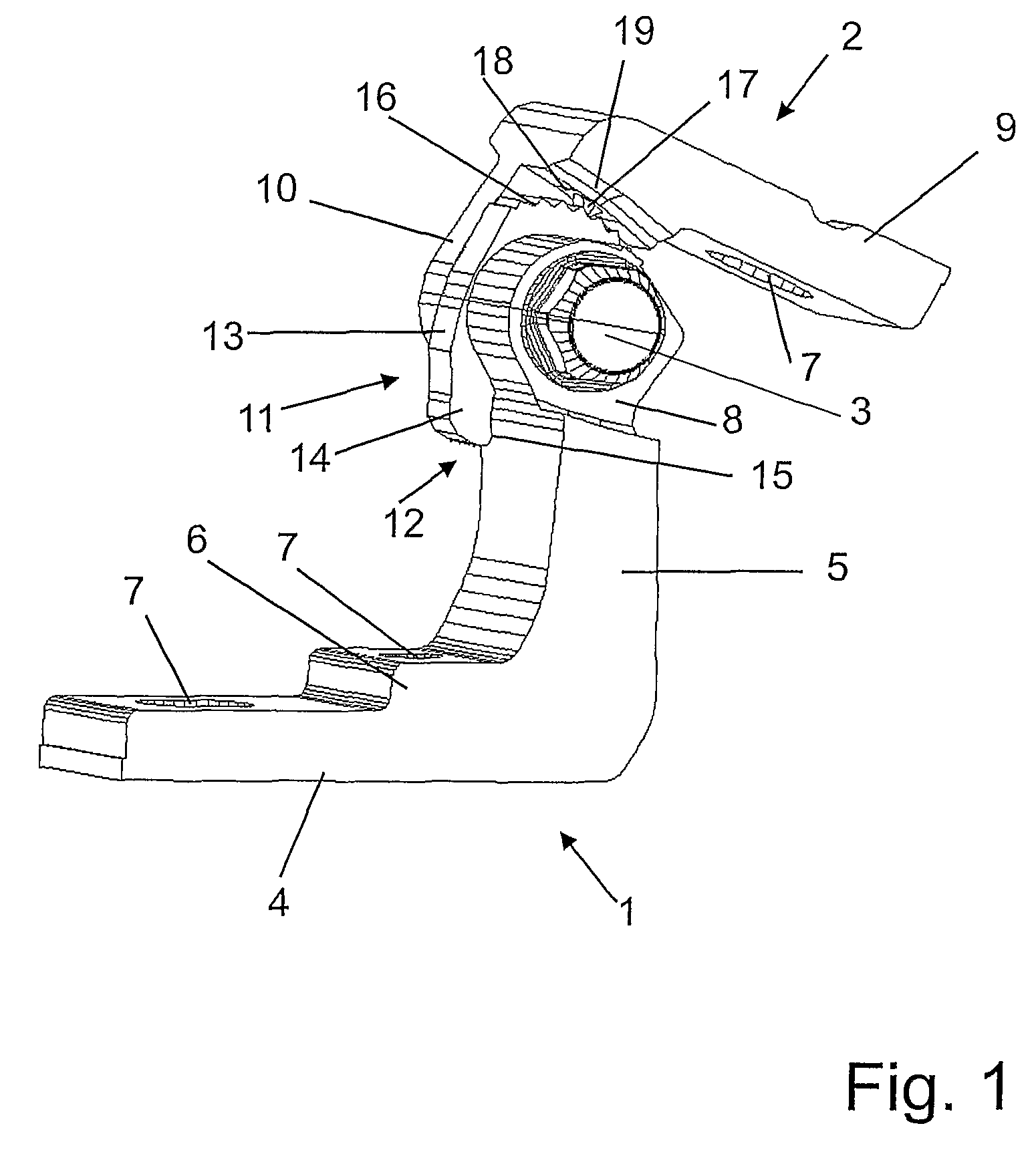
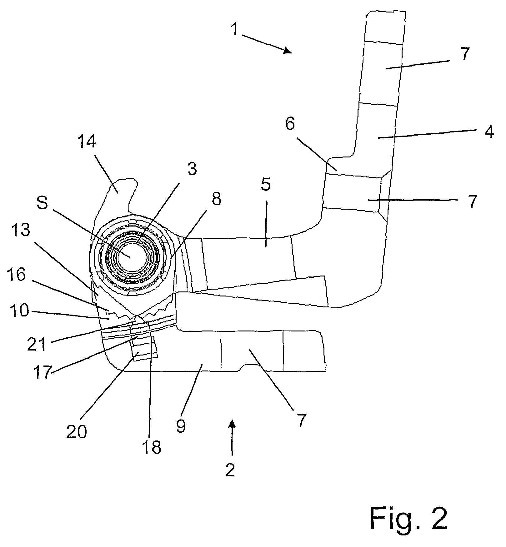
[0017]FIGS. 1, 2 and 3 show a preferred exemplary embodiment of a hinge according to the invention for a vehicle door, in which a first hinge part 1 and a second hinge part 2 are connected to each other pivotably about a hinge pivot axis S by means of a hinge pin 3.

[0018]The first hinge part 1 has an L-shaped configuration with a first limb 4 and a second limb 5, the first limb 4 and the second limb 5 being at an angle of approximately 90° with respect to each other. The first limb 4 has, approximately centrally, a thickened portion 6 which extends as far as the second limb 5, with a first fastening hole 7 being arranged in the thickened portion 6. A second fastening hole 7 is provided at that end of the first limb 4 which faces away from the second limb 5.

[0019]A hinge head 8 is provided at that end of the second limb 5 which faces away from the first limb 4, said hinge head having a hole in which the hinge pin 3 is arranged nonrotatably, the hinge pin 3 having, for example, a circ...


PUM


Abstract

The invention relates to a hinge for a vehicle door, comprising a first hinge part that can be fixed to the door or the door frame, a second hinge part which is fixed to the other of the two components, i.e. the door frame or the door, and a hinge pin that defines a swiveling axis of the hinge and pivotally connects the first hinge part and the second hinge part to each other. The hinge pin is arranged nonrotably on the first hinge part or the second hinge part while being rotatably mounted in the other hinge part. The hinge further comprises an end stop which limits an opening movement of the first hinge part and the second hinge part. In order to create a hinge that allows the vehicle door to be opened securely, an adjusting mechanism which is assigned to the first hinge part or the second hinge part is provided for adjusting the end stop.

Description

BACKGROND[0001]The invention relates to a hinge for a vehicle door.[0002]GB 2 333 124 A shows a hinge for a vehicle door, in which a first hinge part and a second hinge part are connected pivotably to each other by means of a hinge pin. A radially extending projection is arranged on the second hinge part and defines an end stop for the opening movement of the first and second hinge parts, the projection bearing against the second hinge part in the end stop. A disadvantage of this type of hinge is the fact that the opening angle of the hinge is predetermined by the end stop.SUMMARY OF THE INVENTION[0003]An object of the invention is to provide a hinge for a vehicle door, which permits secure opening of the vehicle door.[0004]In accordance with an embodiment of the present invention, a hinge for a vehicle door comprises a first hinge part which can be fastened to either the door or door frame, a second hinge part which can be fastened to the other of the parts, the door or door frame,...

Claims


Application Information

Patent Timeline
IPC IPC(8): E05D11/06
CPCE05D11/06E05D5/062E05Y2900/531Y10T16/5513Y10T16/551Y10T16/54028Y10T16/54044
Inventor RUDZEWSKI, STEPHENSCHREIBER, DIETMARHAJI ZADEH ARMAKI, MEHRDADDELL, GEORG
Owner EDSCHA AG
Learn More