
Physiologic sensor apparatus

a sensor and physiology technology, applied in the field of physiologic sensor apparatus, can solve the problems of power source, data acquisition portion of the device, typical interconnection of power source and device, and achieve the effect of reducing the time for retrieving recorded data and improving data access

Inactive Publication Date: 2006-12-14
SCOPRA SCI & GENIE SEC
View PDF12 Cites 186 Cited by
  • Summary
  • Abstract
  • Description
  • Claims
  • Application Information

AI Technical Summary

Benefits of technology

[0011] The disclosed physiologic sensor apparatus additionally aims at reducing operational cost of operation of healthcare institutions, notably in operating rooms, intensive care wards and general medical care wards. The adoption of this wireless technology reduces costs by:
[0012] Improving reliability of monitoring and reducing measurements errors by reducing movement artefacts;
[0013] positively impacting healthcare and medical staff work efficiency by reducing the number of times sensors need to be uninstalled and reinstalled while having to move patient from one room to another; and
[0014] providing interoperability with both legacy and future telemetry systems, including electronic health records filing, reducing time for retrieving recorded data from a central data base, and improving data access from remote locations.

Problems solved by technology

One drawback of such prior art devices is that the power sources are typically integrated with the data acquisition portion of the device which as a result is bulky and must be worn on a belt strapped around the patient's waste, wrist or arm.
One other drawback is that the data acquisition portion of the device is typically interconnected with the physiological parameter detecting portion using an expensive shielded cable.
These cables are also moderately stiff which gives rise to noise artefacts and the like being introduced into the detected signals.
Furthermore, these cables limit patient mobility and require that health care personal assistance when patient is transported from one location to another.

Method used


Image

  • Physiologic sensor apparatus
  • Physiologic sensor apparatus
  • Physiologic sensor apparatus

Examples


Embodiment Construction

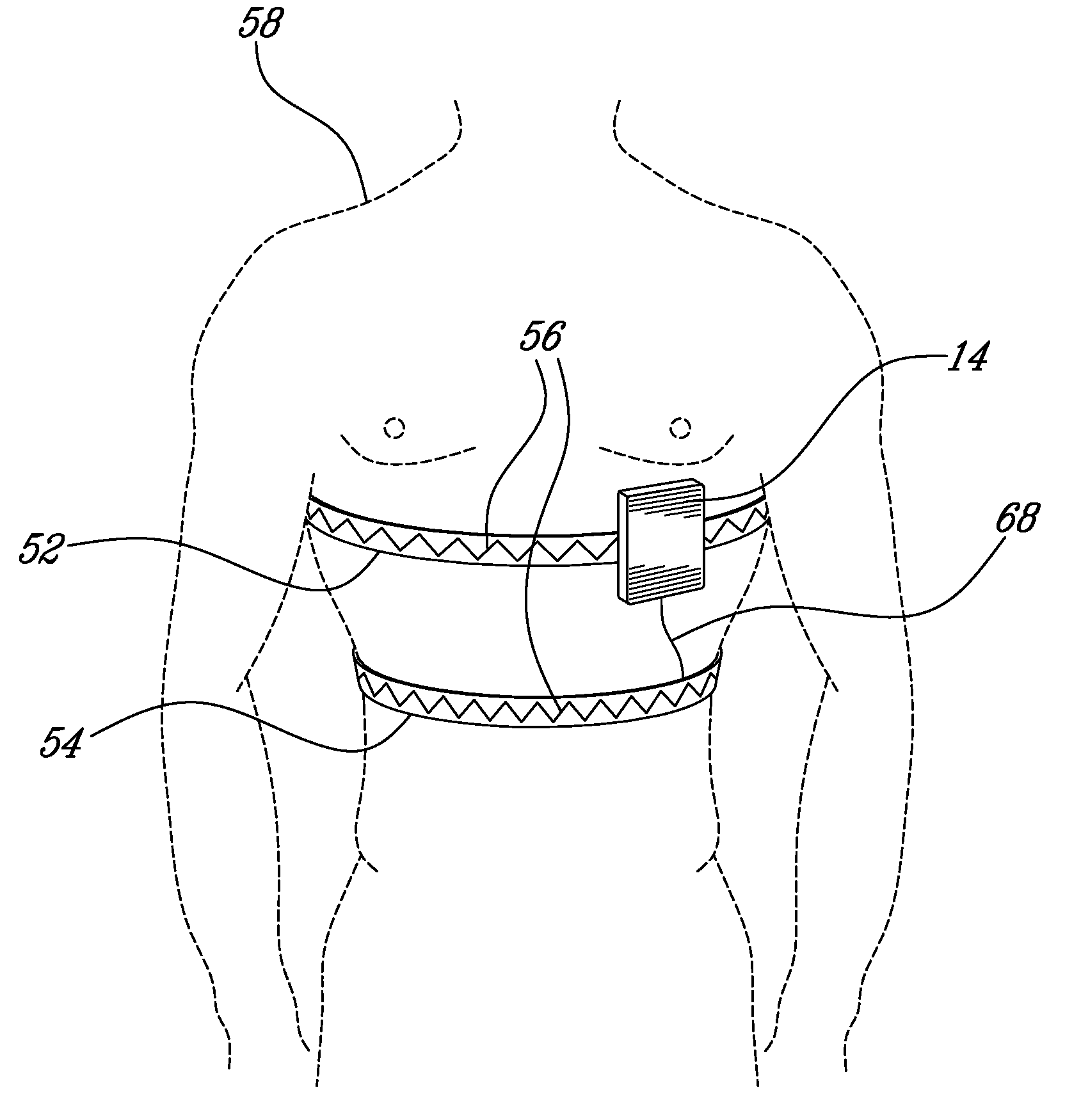
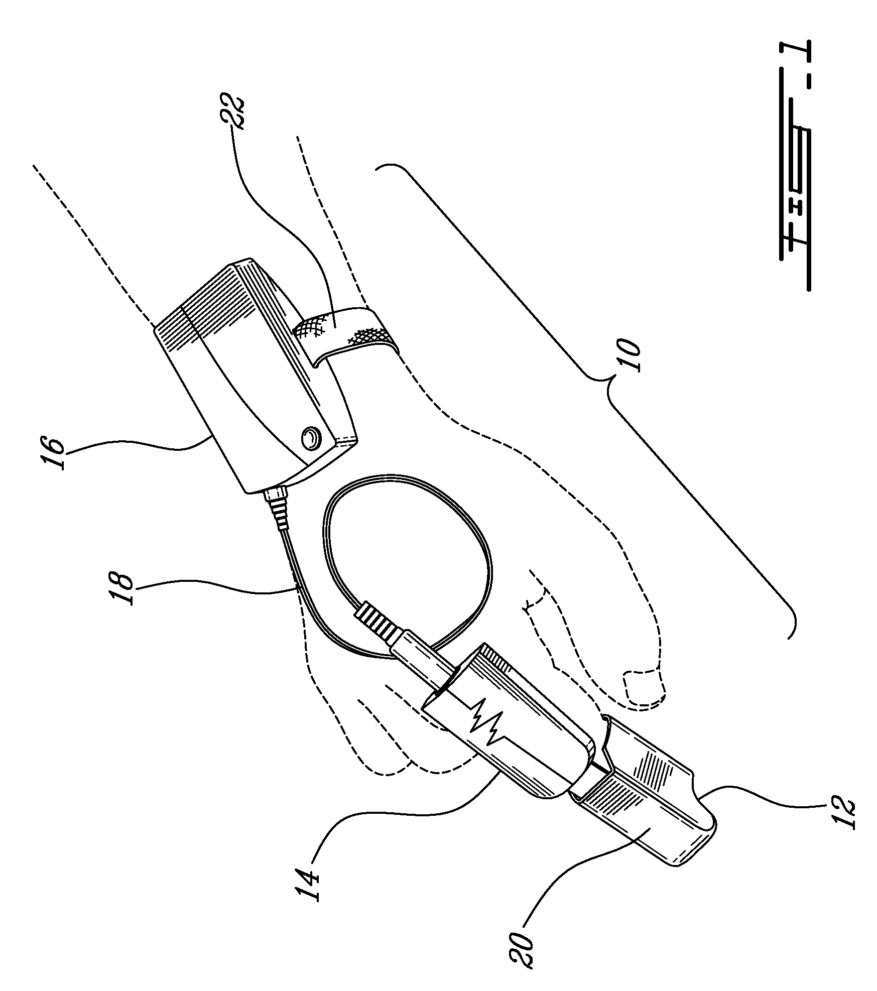
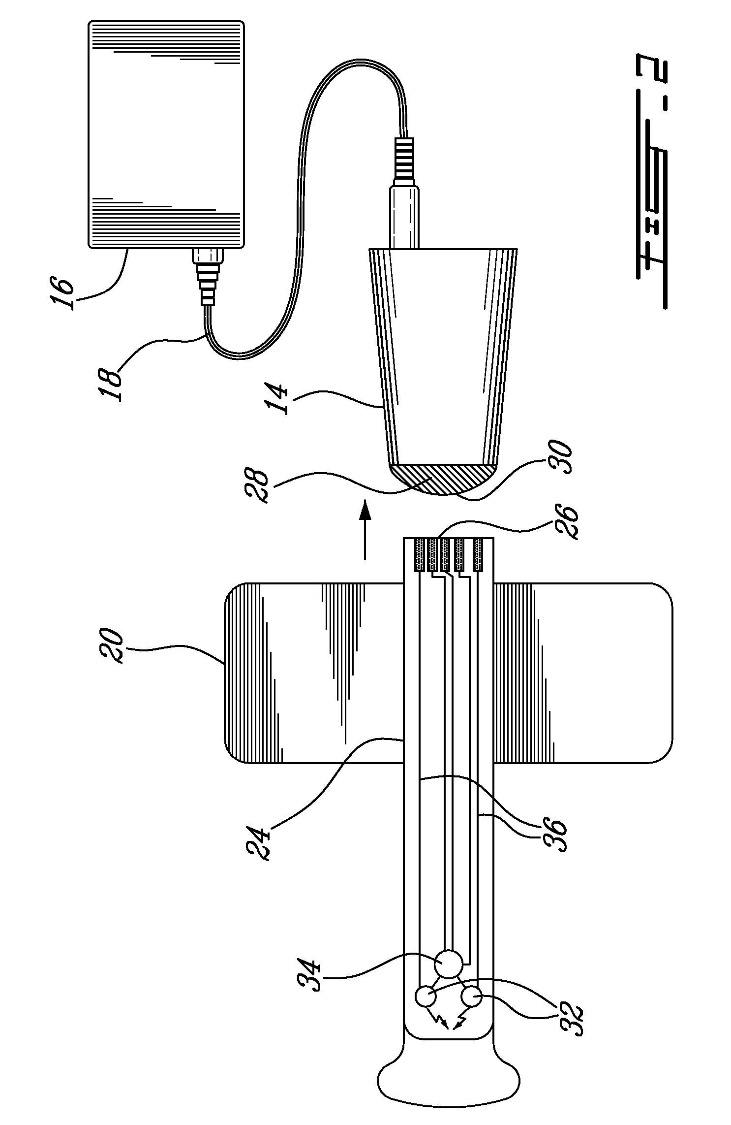
[0022] Referring now to FIG. 1, a physiologic sensor apparatus, generally referred to using the reference numeral 10, will now be described. The physiologic sensor apparatus 10 is comprised of a detector portion 12, an acquisition portion 14 and a power source 16. The power source 16, such as a replaceable battery or rechargeable battery or the like, supplies the acquisition portion 14 with power via an electrical wire 18. The detector portion 12, which can be either reusable or disposable, is secured to a patient through the use of, for example, an adhesive elastic bandage 20 which also provides support to the acquisition portion 14 attached to the detector portion 12 although in an alternative embodiment the acquisition portion 14 could be supported independently of the detector portion 12. Examples of suitable detector portions for use in this arrangement include those manufactured by Masimo and Nellcor, amongst others. Additionally, the power source 16 is mounted, for example, o...


PUM


Abstract

An apparatus for sensing at least one physiological parameter of a patient and transmitting data related to the sensed physiological parameter to an external device. The apparatus comprises a detecting portion comprising at least one sensor interconnected with a connector, an acquisition portion comprising a connector interface configured to receive the connector, electronics for controlling the at least one sensor via the connector interface, receiving data related to the at least one physiological parameter from the at least one sensor via the connector interface and processing the received data, and a wireless interface for transmitting the processed data to the external device, and a power source for supplying energy to the acquisition module.

Description

CROSS REFERENCE TO RELATED APPLICATIONS [0001] The present application claims priority from U.S. Provisional Application No. 60 / 688,716 the entire contents of which is incorporated herein by reference.FIELD OF THE INVENTION [0002] The present invention relates to a physiologic sensor apparatus. In particular, the present invention relates to an apparatus having a multipart part design: a first part housing the detector; a second part housing an acquisition unit comprising a transmitter or transceiver (transmitter / receiver) and a third part housing a power source and which may contain electronics for carrying out electronic power management and / or to perform some less noise critical functions usually done by the acquisition unit. Each part of the design can be individually disposable, reusable and / or rechargeable. BACKGROUND OF THE INVENTION [0003] The prior art reveals a number of sensor devices which collect data related to one or more physiological parameters of a patient and tran...

Claims


Application Information

Patent Timeline
Patent Type & Authority Applications(United States)
IPC IPC(8): A61B5/08A61B5/00A61B5/04
CPCA61B5/0402A61B5/0816A61B5/14552A61B2562/24A61B5/6838A61B2562/182A61B5/6826A61B5/318
Inventor NOEL, MICHELDUMONT, SYLVAIN
Owner SCOPRA SCI & GENIE SEC
Learn More