
Tensioner

a technology of a sleeve and a sleeve is applied in the field of sleeve sleeve sleeve, which can solve the problems of sleeve retracting, and achieve the effects of reducing manufacturing costs, simplifying the structure, and reducing the shock load

Active Publication Date: 2006-12-14
BORG WARNER MORSE TEC JAPAN KK
View PDF6 Cites 50 Cited by
  • Summary
  • Abstract
  • Description
  • Claims
  • Application Information

AI Technical Summary

Benefits of technology

[0013] In the first embodiment of the present invention, when the piston moves in the protruding direction, during operation, the circlip member fitted on the rack teeth of the piston travels along with the piston, and the ring-shaped body of the circlip member contacts and engages with the upper stop surface of the piston bore of the housing. In this state, when the piston moves further in the protruding direction, the rack teeth of the piston travel over the ring-shaped body of the circlip member and the movement of the piston in the protruding direction is thus permitted.
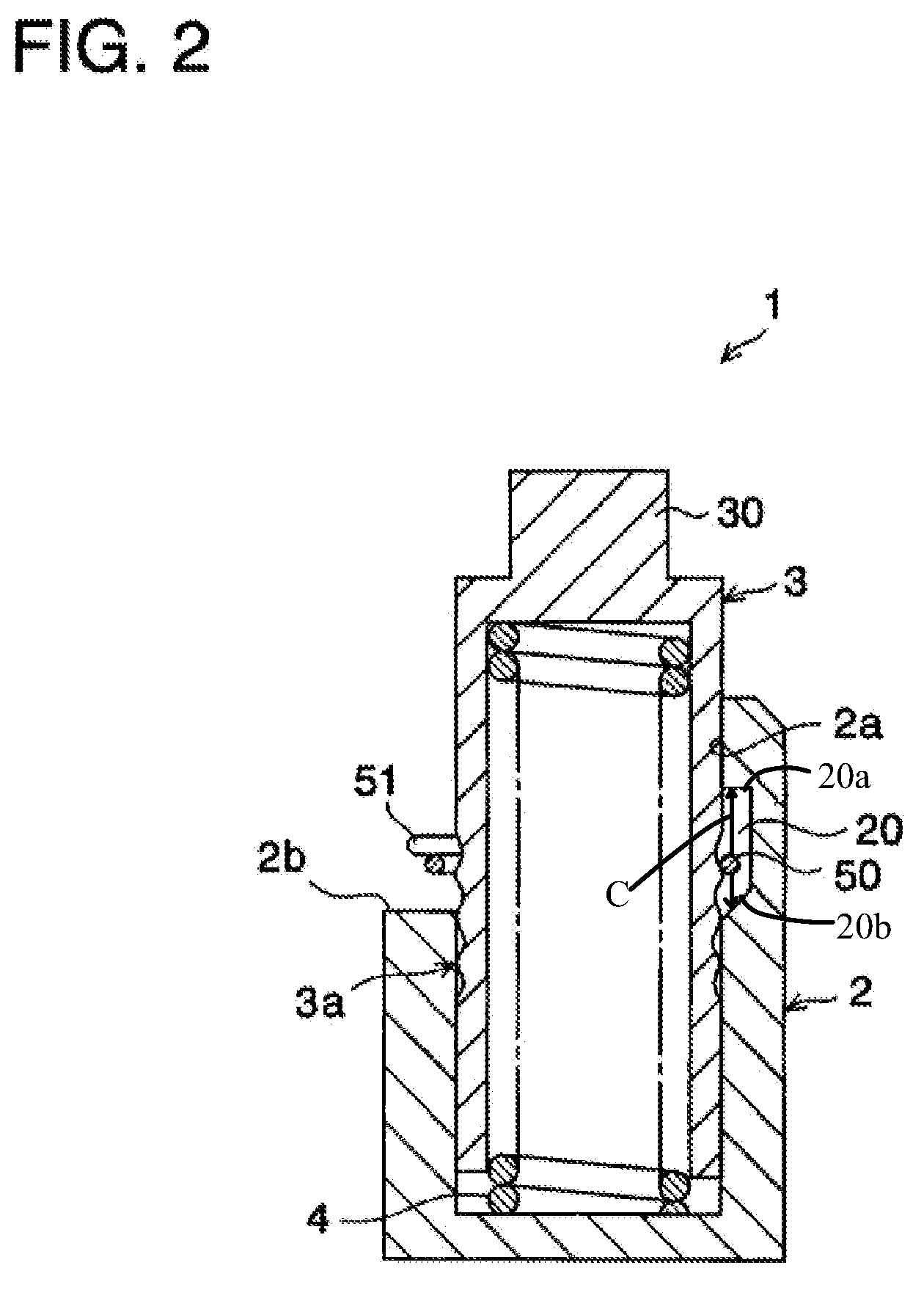
[0014] When the piston moves in the retracting direction, the circlip member fitted on the rack teeth of the piston travels along with the piston and the ring-shaped body of the circlip member contacts and engages with the lower stop surface of the piston bore of the housing. In this state, the piston is locked in the retracting direction through the engagement of the ring-shaped body of the circlip member with the rack teeth of the piston and the lower stop surface of the piston bore, and the movement of the piston in the retracting direction is thus restricted. Also, when the ring-shaped body of the circlip member comes into contact with the lower stop surface of the piston bore, the wavy portion of the ring-shaped body elastically deforms in the axial direction. Thereby, a shock is relieved when the ring-shaped body of the circlip member impacts the lower stop surface of the piston bore thus decreasing the impact sound at the time of retraction of the piston.
[0017] According to the second embodiment of the present invention, when the piston moves in the protruding direction during operation, the circlip member fitted on the rack teeth of the piston travels along with the piston, and the ring-shaped body of the circlip member contacts and engages with the upper stop surface of the piston bore of the housing. In this state, the rack teeth of the piston travel over the ring-shaped body of the circlip member and the movement of the piston in the protruding direction is thus permitted.
[0018] When the piston moves in the retracting direction, the circlip member fitted on the rack teeth of the piston travels along with the piston, and the ring-shaped body of the circlip member contacts and engages with the washer member disposed on the lower stop surface of the piston bore of the housing. In this state, the piston is locked in the retracting direction through the engagement of the ring-shaped body of the circlip member with the rack teeth of the piston and the washer on the lower stop surface of the piston bore, thus restricting the movement of the piston in the retracting direction. Also, when the ring-shaped body of the circlip member comes into contact with the washer member on the lower stop surface of the piston bore, the washer member elastically deforms in the axial direction. Thereby, a shock is relieved when the ring-shaped body of the circlip member impacts the washer member and the impact sound at the time of retraction of the piston is thus decreased.
[0021] In this case, during operation, when the piston moves in the retracting direction, the circlip member fitted on the rack teeth of the piston travels the clearance formed between the circlip member and the lower stop surface. Thereby, when the increased tension in the chain applies an excessive shock load to the piston, the excessive shock load is prevented from directly and immediately acting on the ring-shaped body engaged with the rack teeth of the piston.
[0022] The tensioner may be a mechanical tensioner. In this case, there is no need to provide an oil circuit that makes the entire structure of the tensioner complicated, simplifying the structure and reducing the manufacturing cost.

Problems solved by technology

Also, during operation, when tension in the chain increases due to resonance of a chain span, an excessive shock load from the chain acts on the piston of the tensioner, causing the piston to retract into the housing of the tensioner.

Method used


Image

  • Tensioner
  • Tensioner
  • Tensioner

Examples


Embodiment Construction

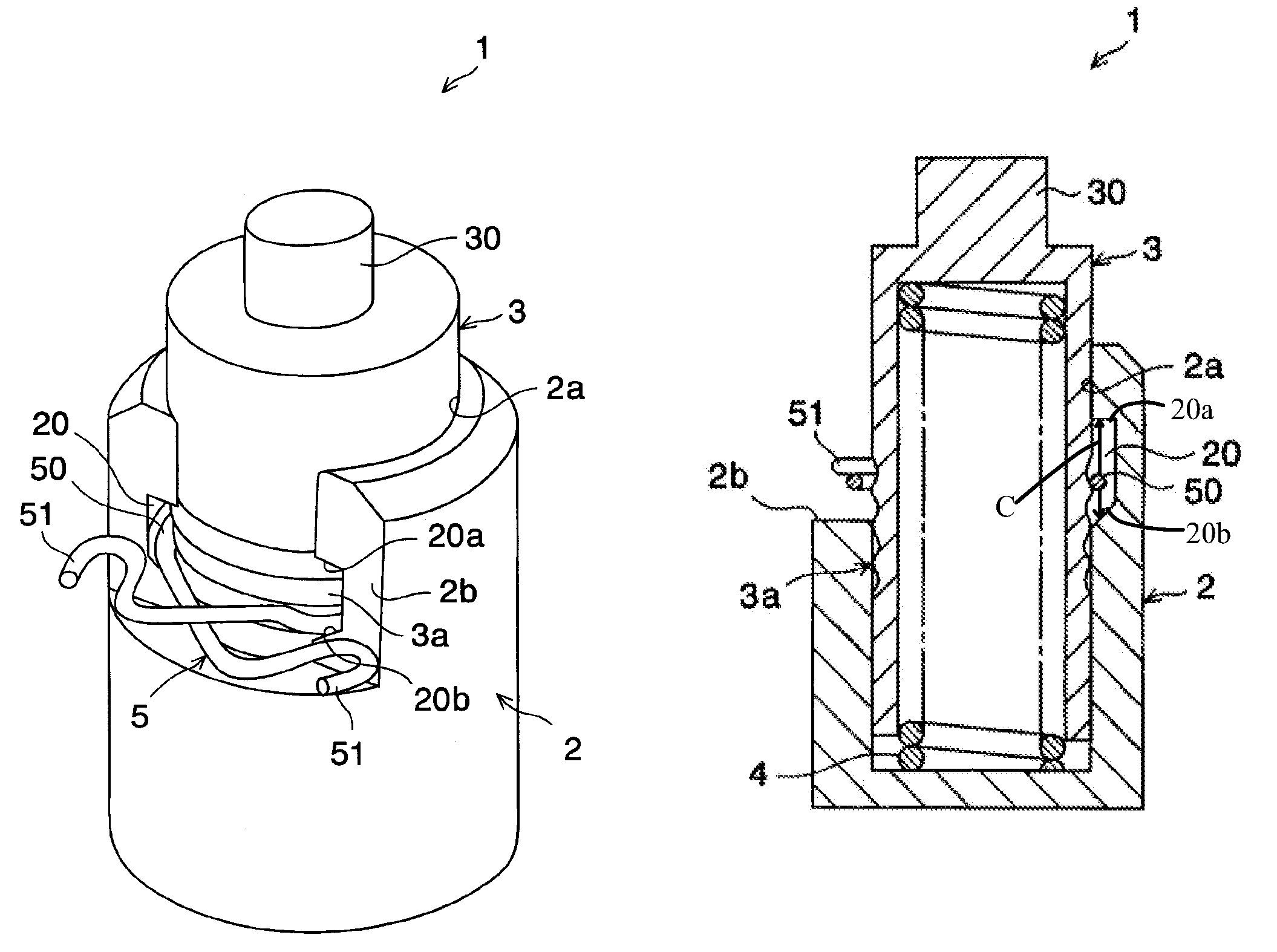
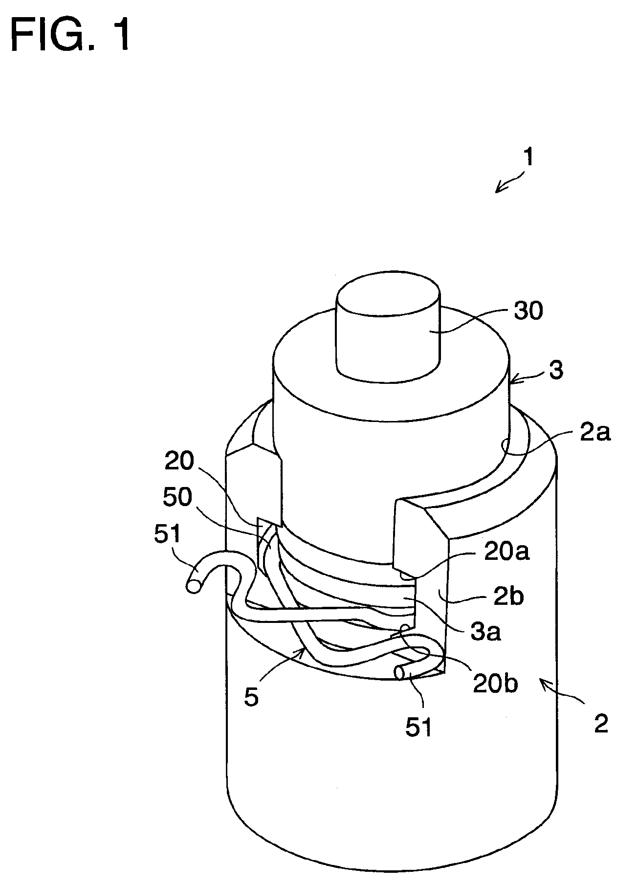
[0029] FIGS. 1 to 5 show a tensioner according to an embodiment of the present invention. As shown in FIGS. 1 and 2, a tensioner 1 is comprised of a housing 2 having an axially extending piston bore 2a and a notch 2b formed at an open end of the piston bore 2a and radially connecting with the piston bore 2a. The hollow piston 3 is slidably supported in the piston bore 2a and has rack teeth 3a (see FIG. 3) formed on the outer circumferential surface of the piston 3. The piston is biased in the protruding direction from the housing by a piston spring 4 provided in the piston bore 2a. A circlip member 5 fits in the rack teeth 3a of the piston 3.

[0030] As shown in FIG. 4, the circlip member 5 is formed of an expandable ring-shaped body 50 that is engageable with the rack teeth 3a of the piston 3, and has a pair of operatable handle portions 51 with which an operator may expand the ring-shaped body 50. The handle portions 51 extend to the outside of the housing 2 through the notch 2b fo...


PUM


Abstract

A tensioner that includes a piston supported slidably in a piston bore formed in a housing, a piston spring biasing the piston in the protruding direction, and a circlip member having an expandable ring-shaped body that is engageable with the rack teeth of the piston. In the piston bore, the ring-shaped body of the circlip member is adapted to engage with an upper and lower stop surface. The rack teeth of the piston are formed in such a shape that when the ring-shaped body of the circlip member engages with the upper stop surface of the piston bore, the piston is permitted to move in the protruding direction and, when the ring-shaped body of the circlip member engages with the lower stop surface of the piston bore, the piston restricts movement in the retracting direction.

Description

REFERENCE TO RELATED APPLICATIONS [0001] This application claims an invention which was disclosed in Japanese application number 2005-172565, filed Jun. 13, 2005, entitled “TENSIONER.” The benefit under 35 USC§ 119(a) of the Japanese application is hereby claimed, and the aforementioned application is hereby incorporated herein by reference. BACKGROUND OF THE INVENTION [0002] 1. Field of the Invention [0003] The present invention relates to a tensioner with a ratchet mechanism having a circlip member that engages with the rack teeth formed on the outer circumferential surface of a piston. More particularly, the invention relates to an improvement in structure to decrease an impact sound that occurs when the external force from the chain causes the piston to retract. [0004] 2. Description of Related Art [0005] Generally, in timing chains for valve drives of internal combustion engines, camshaft chains in use for a camshaft-camshaft drive, and balancer chains, have tensioners that are...

Claims


Application Information

Patent Timeline
Patent Type & Authority Applications(United States)
IPC IPC(8): F16H7/08F16H7/22
CPCF16H7/0848F16H2007/0855F16H2007/0853F16H2007/0806
Inventor NARITA, KINZOWAKE, JUNICHIBARRETTE, SIMON
Owner BORG WARNER MORSE TEC JAPAN KK
Learn More