
Roll-former apparatus with rapid-adjust sweep box

a technology of rolling former and sweep box, which is applied in the direction of metal rolling arrangement, manufacturing tools, transportation and packaging, etc., can solve the problems of increasing in-process inventory, increasing dimensional variability, and adding cos

Active Publication Date: 2006-12-14
SHAPE CORP
View PDF38 Cites 22 Cited by
  • Summary
  • Abstract
  • Description
  • Claims
  • Application Information

AI Technical Summary

Benefits of technology

[0013] In yet another aspect of the present invention, an apparatus includes a sweep apparatus having a primary bending roller tangentially engaging the continuous beam. An opposing holding roller is adjustable to different positions downstream of the primary bending roller and holds the continuous beam against the primary bending roller to cause a desired sweep to be imparted into the continuous beam. At least one stabilizing roller tangentially engages the continuous beam upstream of the primary bending roller. First, second, and third drive motors drive the primary bending roller, the holding roller and the stabilizing roller, respectively. A controller independently controls a drive speed of each of the first, second, and third rollers to control and manage stress on the continuous beam while in the sweep station in order to form a more consistent swept shape of the continuous beam.

Problems solved by technology

However, secondary operations add cost, increase dimensional variability, and increase in-process inventory, and also present quality issues.
Nonetheless, it is important to understand that bumper beams for modern vehicles present a substantial increase in difficulty due to their relatively large cross-sectional size and non-circular cross-sectional shape, the high strength of materials used herein, the very tight dimensional and tolerance requirements of vehicle manufacturers, the cost competitiveness of the vehicle manufacturing industry, and the high speed at which modern roll-forming lines run.
However, even though the sweep station is adjustable, it does not necessarily mean that the apparatus is able to manufacture beams having multiple sweep radii therein.
Certainly, non-uniform longitudinal curvatures cannot be uniformly repeated formed along a length of a continuous beam by manual means and further cannot productively and efficiently be made in high speed rollforming operations using slow-acting automated equipment.
Further, there is no teaching in Renzzulla '451 to form a multi-swept beam using a computer controlled sweep apparatus in continuation with a coordinated computer-controlled cut-off device adapted to cut off individual bumper beam sections from the continuous beam at specific locations related to particular sweep regions.
Further, based on the density of threads suggested by the FIGS. 1-2 (and also based on the lack of any discussion in Renzzulla '451 regarding automated “cyclical” adjustment), it appears that the device of Renzzulla '451 suffers from the same problem as manually adjustable sweep stations—i.e., that it cannot be adjusted fast enough to cause multiple sweeps within a 4 to 5 foot span along the continuous roll-formed beam, given normal relatively fast linear speeds of roll-forming mills.
There is potentially another more fundamental problem in sweep station of the Renzzulla '451 patent when providing tight sweeps (i.e., sweeps with short radii) along a continuous beam.
This makes it very it difficult to control twisting and snaking, difficult to control undesired warping and wandering, and also difficult to control dimensional variations.
These variables combine and lead to unpredictability of deformation in the beam and the beam walls.
In other words, as the unsupported distance increases (i.e., as tighter sweeps are formed), the problem of uncontrolled movement and deflection of the beam walls becomes worse .
. . potentially leading to dimensional and quality problems.
This large unsupported distance allows the walls of the roll-formed beam to wander and bend uncontrollably as deformation occurs in this area of no support.

Method used


Image

  • Roll-former apparatus with rapid-adjust sweep box
  • Roll-former apparatus with rapid-adjust sweep box
  • Roll-former apparatus with rapid-adjust sweep box

Examples


Embodiment Construction

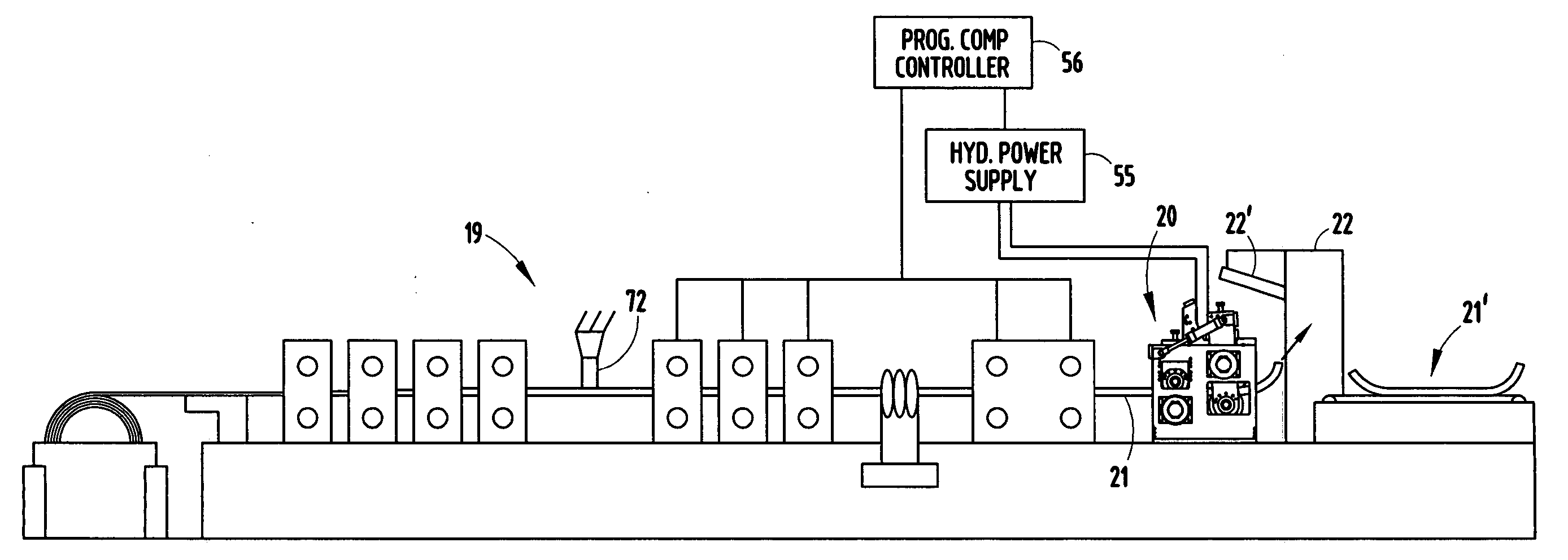
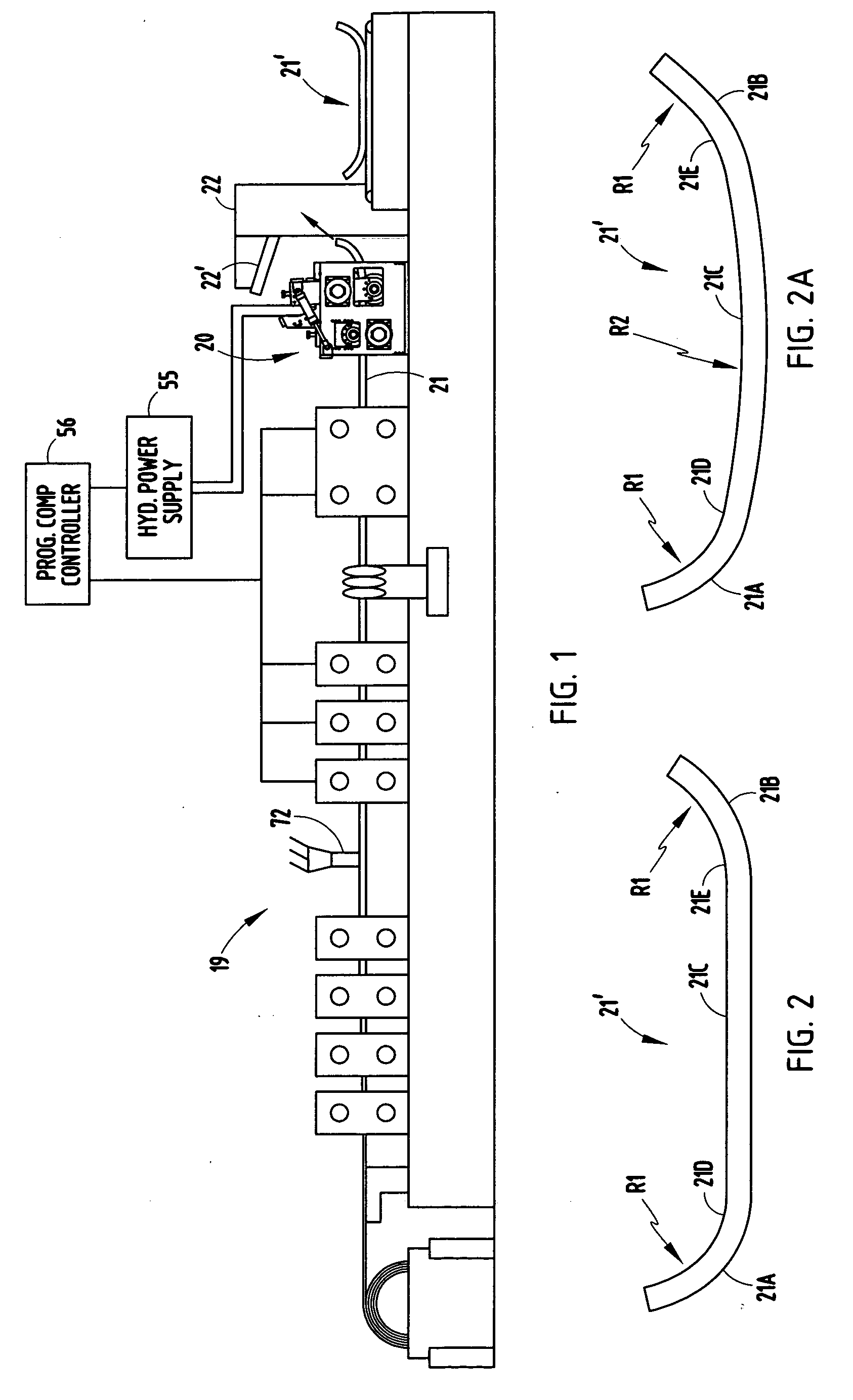
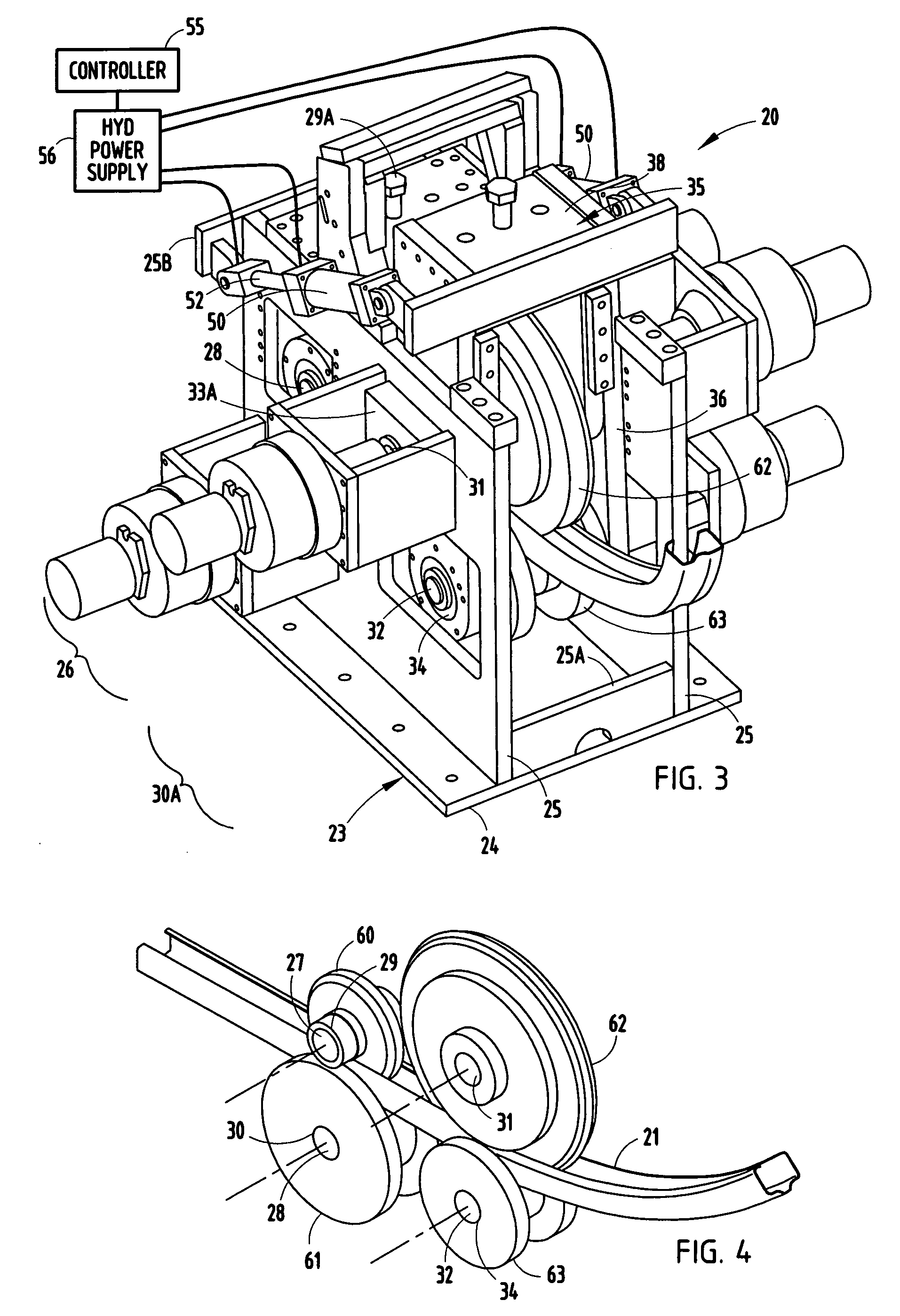
[0024] The present roll-former mill apparatus 19 (FIG. 1) is adapted to make roll-formed vehicle bumper beams 21′ (also called “bumper beam segments” or “reinforcement beams” herein) having a constant cross-sectional shape and consistent dimensional shape, but having a varied longitudinal curvature formed by a sweep station 20. The sweep station 20 is positioned in-line with and at an output end of the roll-former apparatus 19. The roll-forming portion of the apparatus 19 is not unlike that shown in FIG. 4 of Sturrus U.S. Pat. No. 5,092,512, and the teachings of the Sturrus '512 patent are incorporated herein in their entirety. The present sweep station 20 includes a multi-roller system that is computer-controlled and automated and that is arranged to permit quick accurate adjustment, allowing the sweeping operation to be repeatedly varied during the roll-forming process in order to form uniform dissimilar sweep radii along a length of the beam segments as an integral part of the ro...


PUM

PropertyMeasurementUnit
Speedaaaaaaaaaa
Lengthaaaaaaaaaa
Speedaaaaaaaaaa

Abstract

A computer controlled roll-forming apparatus is adapted to provide a repeating pattern of different longitudinal shapes to a continuous beamon the fly” during the roll-forming process. A sweep station on the apparatus includes a primary bending roller tangentially engaging the continuous beam along the line level and an armature for biasing the continuous beam against the primary bending roller for a distance partially around a downstream side of the primary bending roller to form a sweep. Further, actuators adjustably move the armature at least partially around the downstream side of the primary bending roller between at least first and second positions for imparting multiple different longitudinal shapes into the continuous beam. In one form, the apparatus also includes a coordinated cut-off, so that when separated into bumper beam segments, the ends of the individual beam segments have a greater sweep than their center sections.

Description

BACKGROUND [0001] The present invention relates to a roll-forming apparatus with a sweep station adapted to impart multiple sweeps (i.e., non-uniform longitudinal curvatures) into a roll-formed beam. [0002] Roll-formed bumper beams have recently gained wide acceptance in vehicle bumper systems due to their low cost and high dimensional accuracy and repeatability. Their popularity has increased due to the ability to sweep (i.e., provide longitudinal curves) in the roll-formed beam sections in order to provide a more aerodynamic appearance. For example, one method for roll-forming a constant longitudinally curved beam is disclosed in Sturrus U.S. Pat. No. 5,092,512. [0003] The aerodynamic appearance of vehicle bumpers is often further enhanced by forming a section of the front surface at ends of the bumpers rearwardly at an increased rate from a center of the bumper beam. This is typically done by secondary operations on the bumper beam. Exemplary prior art secondary operations for do...

Claims


Application Information

Patent Timeline
IPC IPC(8): B21D5/04
CPCB21D5/08B21D53/88B21D7/028B21D5/04B21D5/14
Inventor LYONS, BRUCE W.GOULD, BRYAN E.DODD, JAMES H.HEINZ, RICHARD D.
Owner SHAPE CORP
Learn More