
Throughput Maximization Using Quantized Rate Control in Multiple Antenna Communication

a multiple antenna communication and rate control technology, applied in the field of wireless communication systems, can solve the problems of low probability of reliable decoding, inability to obtain channel state information, and receivers usually limited to using feedback links with very limited capacity, so as to optimize the throughput of the system, improve system throughput performance, and save power

Inactive Publication Date: 2006-12-07
NEC CORP
View PDF8 Cites 40 Cited by
  • Summary
  • Abstract
  • Description
  • Claims
  • Application Information

AI Technical Summary

Benefits of technology

[0005] A feedback link between a receiver and a transmitter in a multiple antenna communication system is used to control the transmission rate and thereby improve system throughput performance. An optimized quantized rate control design is disclosed which enables a receiver to determine a transmission rate from an optimized finite set of transmission rates based on an estimate of channel conditions. The receiver can then use a limited feedback link to communicate the selected transmission rate back to the transmitter, the selected transmission rate serving to optimize throughput of the system for a given average power. Equivalently, for a targeted throughput, power savings can be achieved through the use of the quantized rate control mechanism. In one embodiment, an adaptive gradient search technique can be utilized to efficiently find the optimal rate allocations. The disclosed rate control design is advantageously of low complexity and requires a very low-rate feedback link (as little as a few bits per block of transmission) to achieve potentially significant gains in system throughput.

Problems solved by technology

The time varying nature of the channel quality in wireless environments (referred to as “fading”) causes random fluctuations in the received power level and, as a result, can lower the probability of reliable decoding.
Unfortunately, in practical systems, it is often only possible to obtain an estimate of the channel state information at the receiver.
Moreover, the receiver is usually limited to using a feedback link with a very limited capacity (e.g., a few bits of feedback per block of transmission) when providing the channel state information to the transmitter.

Method used


Image

  • Throughput Maximization Using Quantized Rate Control in Multiple Antenna Communication
  • Throughput Maximization Using Quantized Rate Control in Multiple Antenna Communication
  • Throughput Maximization Using Quantized Rate Control in Multiple Antenna Communication

Examples


Embodiment Construction

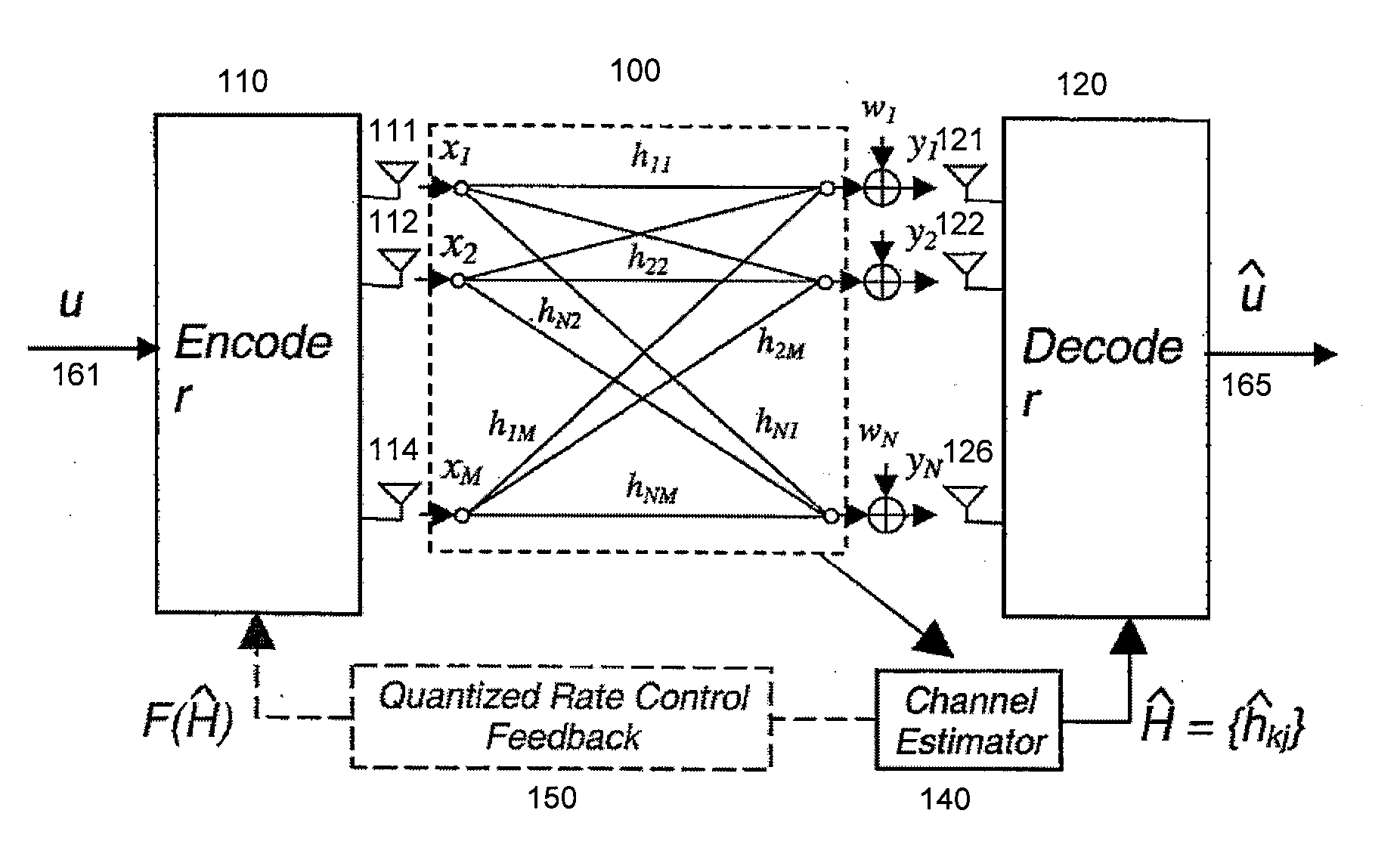
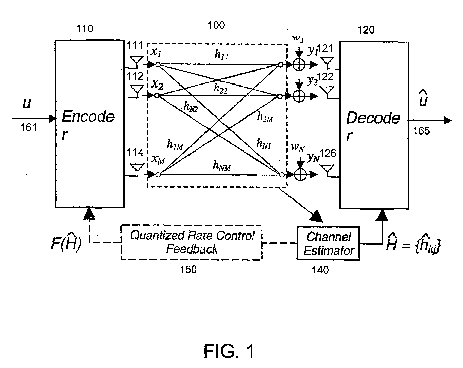
[0009]FIG. 1 is an abstract illustration of a coded multiple-input multiple-output (MIMO) system, suitable for practice of an embodiment of the invention.

[0010] As depicted in FIG. 1, the multiple antenna system has M transmit antennas 111, 112, . . . 114 and N receive antennas 121, 122, . . . 126 which communicate across a channel 100. It is assumed that the system utilizes some form of coding scheme with an encoder 110 at the transmitter and a corresponding decoder 120 at the receiver. The multiple antenna system can be modeled as follows: the received signal can be represented by a vector yN×1 such that

y=Hx+w,  (1)

where xM×1 is a vector representing the transmitted symbols, HN×M represents the channel matrix, and wN×1 is a circularly symmetric complex additive white Gaussian noise with zero mean and variance one. Consider a block fading channel model in which the channel remains constant during transmission of each packet (or codeword of length T) and changes independently fr...


PUM


Abstract

A feedback link between a receiver and a transmitter in a multiple antenna communication system is used to control the transmission rate and thereby improve system throughput performance.

Description

[0001] This application claims the benefit of and is a nonprovisional of U.S. Provisional Application No. 60 / 686,358, entitled “THROUGHPUT MAXIMIZATION USING QUANTIZED RATE CONTROL IN MULTIPLE ANTENNA COMMUNICATION SYSTEM,” filed Jun. 1, 2005, the contents of which are incorporated by reference herein.BACKGROUND OF INVENTION [0002] The invention relates generally to wireless communication systems and, more particularly, to rate control in multiple antenna communication systems. [0003] It has been shown that wireless communication systems with multiple antennas can provide significant performance improvements and achievable data rates over single antenna systems, in particular in fading environments. The time varying nature of the channel quality in wireless environments (referred to as “fading”) causes random fluctuations in the received power level and, as a result, can lower the probability of reliable decoding. The attempted transmission rate may exceed the instantaneous channel ...

Claims


Application Information

Patent Timeline
IPC IPC(8): H04B7/00
CPCH04B7/04H04L1/0002H04W52/248H04L1/0618H04L1/0026
Inventor KHOJASTEPOUR, MOHAMMAD A.WANG, XIAODONGMADIHIAN, MOHAMMAD
Owner NEC CORP
Learn More