
Pose estimation based on critical point analysis

a technology of critical point analysis and pose estimation, applied in the field of machine vision, can solve the problems of high cost of 3d camera system, complex equipment needed to capture image information,

Active Publication Date: 2006-12-07
THE OHIO STATE UNIV RES FOUND +1
View PDF9 Cites 52 Cited by
  • Summary
  • Abstract
  • Description
  • Claims
  • Application Information

AI Technical Summary

Problems solved by technology

One problem with conventional techniques for pose estimation is the complexity and expense of equipment needed to capture image information.
The 3D camera system is also very expensive.

Method used


Image

  • Pose estimation based on critical point analysis
  • Pose estimation based on critical point analysis
  • Pose estimation based on critical point analysis

Examples


Embodiment Construction

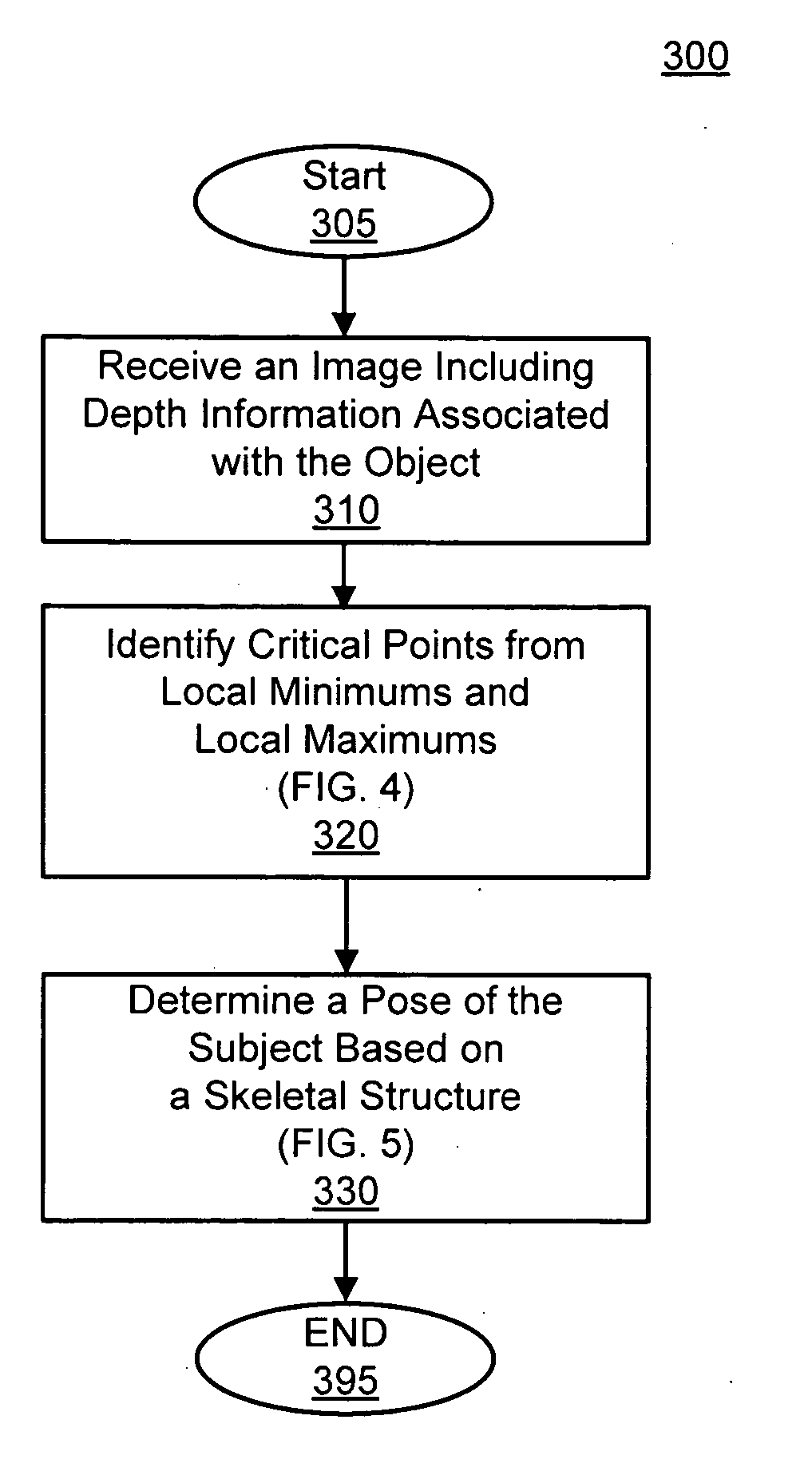
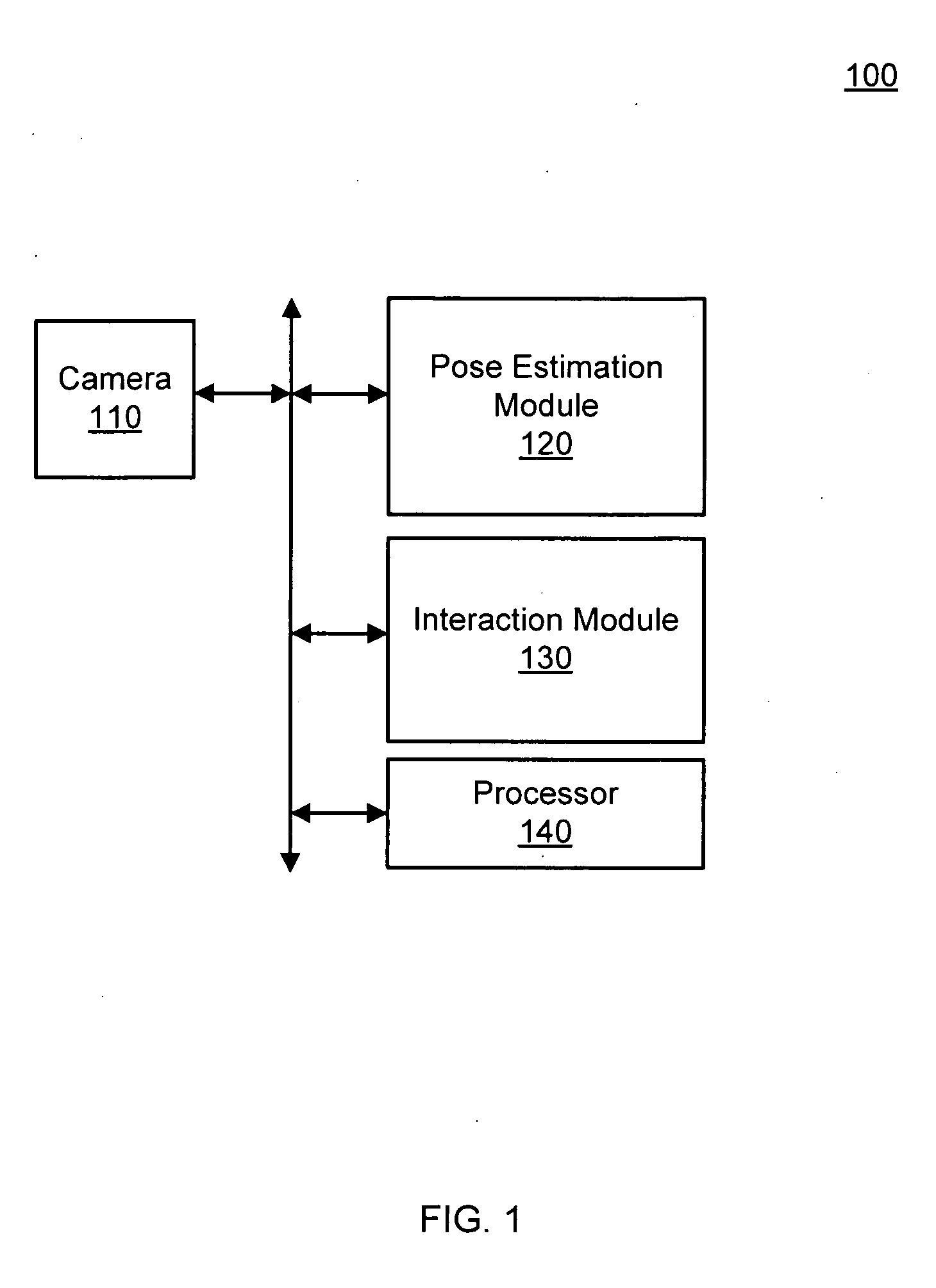
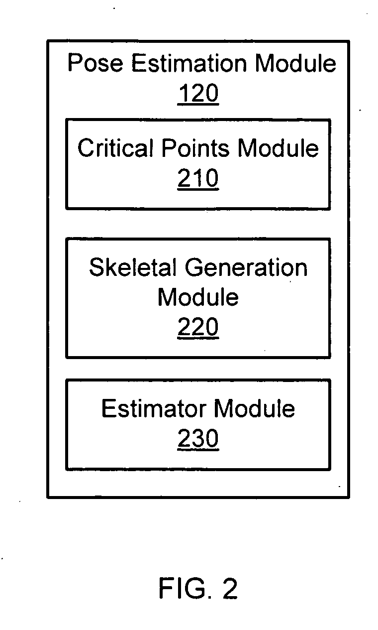
[0026] Methods and systems for estimating a position of a subject are described. The subject can be, for example, a human, an animal, or a robot. As the subject is in motion, or is performing various actions, the subject holds different poses over time. In one embodiment, component point analysis is employed to determine a position of the subject at a certain time. By tracking positions over time, the motion of action of the subject can be determined. For example, a robot can react to visual cues of a human such as go left, speed up, and stop. FIGS. 1 and 2 show an exemplary system implementing a method for pose estimation, and FIGS. 3-6 show an exemplary method for pose estimation. One of ordinary skill in the art will understand that, give the description herein, additional embodiments are possible.

[0027]FIG. 1 is a block diagram illustrating a system 100 for pose estimation according to one embodiment of the present invention. System 100 comprises a depth camera 110, a pose esti...


PUM


Abstract

Methods and systems for estimating a pose of a subject. The subject can be a human, an animal, a robot, or the like. A camera receives depth information associated with a subject, a pose estimation module to determine a pose or action of the subject from images, and an interaction module to output a response to the perceived pose or action. The pose estimation module separates portions of the image containing the subject into classified and unclassified portions. The portions can be segmented using k-means clustering. The classified portions can be known objects, such as a head and a torso, that are tracked across the images. The unclassified portions are swept across an x and y axis to identify local minimums and local maximums. The critical points are derived from the local minimums and local maximums. Potential joint sections are identified by connecting various critical points, and the joint sections having sufficient probability of corresponding to an object on the subject are selected.

Description

CROSS-REFERENCE TO RELATED APPLICATION [0001] This application claims priority under 35 U.S.C. §119(e) to co-pending U.S. Provisional Patent Application No. 60 / 663,020, entitled “Pose Estimation Based on Critical Point Analysis,” filed on Mar. 17, 2005, the subject matter of which is incorporated by reference herein in its entirety.BACKGROUND OF THE INVENTION [0002] 1. Field of the Invention [0003] The present invention relates to machine vision, and more specifically, to machine-based estimation of poses using critical point analysis. [0004] 2. Description of the Related Art [0005] Conventional techniques for machine vision allow a robot or other machine to recognize objects. The objects can be recognized for navigation around the objects, retrieval of the objects, or other purposes. Conventional techniques for pose estimation detect various objects of a subject such as body parts of a human. Additionally, pose estimation can determine an orientation of the body part. [0006] One pr...

Claims


Application Information

Patent Timeline
IPC IPC(8): G06K9/46
CPCG06K9/00362G06T2207/30196G06T7/0046G06K9/00375G06T7/75G06V40/10G06V40/107G06V20/10
Inventor FUJIMURA, KIKUOZHU, YOUDING
Owner THE OHIO STATE UNIV RES FOUND
Learn More