On-vehicle alternator with brush/slip ring structure

a technology of slip ring and alternator, which is applied in the direction of current collectors, dynamo-electric machines, supports/encloses/casings, etc., can solve the problems of affecting the operation of the alternator

Active Publication Date: 2006-12-07
DENSO CORP
View PDF12 Cites 28 Cited by
  • Summary
  • Abstract
  • Description
  • Claims
  • Application Information

AI Technical Summary

Benefits of technology

[0010] The present invention has been made in view of the situations described above, and has an object of providing an alternator that has the capability of easily promoting the discharge of inside-caused dust matters to the outside of the alternator.
[0011] Moreover, the present invention has another object of providing an alternator that has the capability of, in addition to the above promotion, preventing foreign matters from coming to brushes whatever the alternator is installed to various types of vehicles, Thus the brushes have a higher environmental resistance performance in various kinds of road conditions.
[0013] Hence, thanks to the first and second air-ventilating ports, a ventilating passage communicating, at least, between the inner space containing the slid portions of the brushes on the slip rings to an outside of the alternator is formed. The second air-ventilating port is able to take air into the inner space containing the brushes, thus positively help the air flow out from the inner space containing the slid portions of the brushes toward the outside of the alternator. Accordingly, the ventilating passage positively causes a flow of air to pass from the inner space containing the slid portions of the brushes on the slip rings to an outside of the alternator. The discharge of inside-caused dust matters to the outside of the alternator is promoted. For example, such dust matters are powder dust generated by the slide operations of the brushes on the slip rings. When the first air-ventilating port is assigned to the air discharge port and the second one is assigned to the air-intake port, a flow of air is generated from the second air-ventilating port to the first air-ventilating port. Hence such power dust is well discharged through the first air-ventilating port.
[0015] Hence, in addition to the advantage that the inside-caused dust matters are promoted to be discharged outside, the sealing members prevent foreign matters from reaching brushes, whatever the alternator is installed to various types of vehicles, so that the brushes have a higher environmental resistance performance in various kinds of road conditions.
[0016] A second aspect of the present invention is to provide an alternator to be mounted on a vehicle, comprising: slip rings fixed on a rotary shaft and rotatable together with the rotary shaft; brushes slidable on the slip rings; a brush holder accommodating the brushes therein; a slip-ring cover covering the slip rings as well as the brush holder; a rear cover covering electronic components including the brushes; and ventilating means for positively causing a flow of air from an inner space containing slid portions of the brushes on the slip rings to an outside of the alternator.
[0018] The second and third aspects of the present invention also provide an advantage in that the discharge of inside-caused dust matters toward the outside of the alternator is promoted.

Problems solved by technology

However, the above various structures disclosed by the conventional references have faced a concern that foreign matters (e.g., mud, dust, water) cannot be prevented well from coming into an inner space in which the brushes are positioned.
This concern is especially true of off-road vehicles, because such off-road vehicles are frequently made to run on rough roads.
If such foreign matters are allowed to come into the inner space, there arises a problem that environmental resistance of the brushes is weakened.
However, this installation has a further difficulty, because passages for charging and discharging cooling air should be left, and thus difficult to prevent foreign matters (such as water) from coming in.
Installing the above casing also increases costs for manufacturing alternators.

Method used


Image

  • On-vehicle alternator with brush/slip ring structure
  • On-vehicle alternator with brush/slip ring structure
  • On-vehicle alternator with brush/slip ring structure

Examples


Embodiment Construction

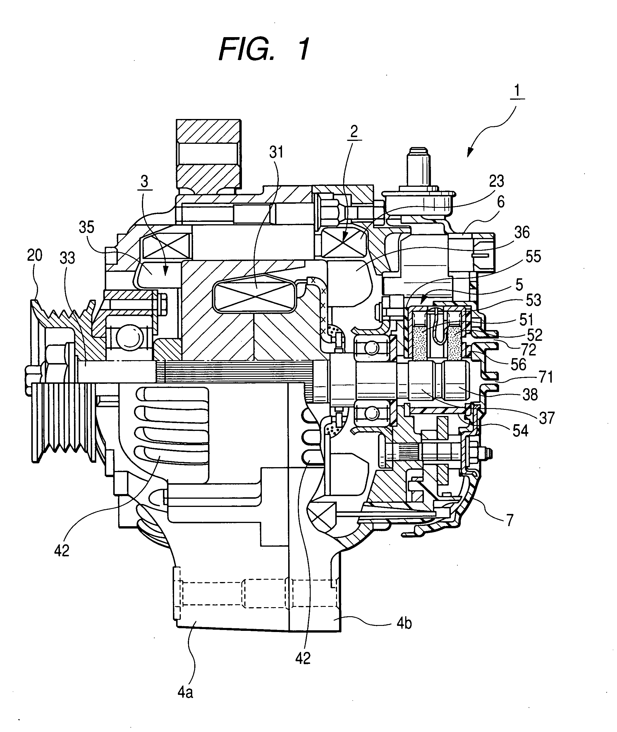
[0027] Referring to FIGS. 1 to 6, an alternator to be mounted on a vehicle (on-vehicle AC alternator) according to an embodiment of the present invention will now be described.

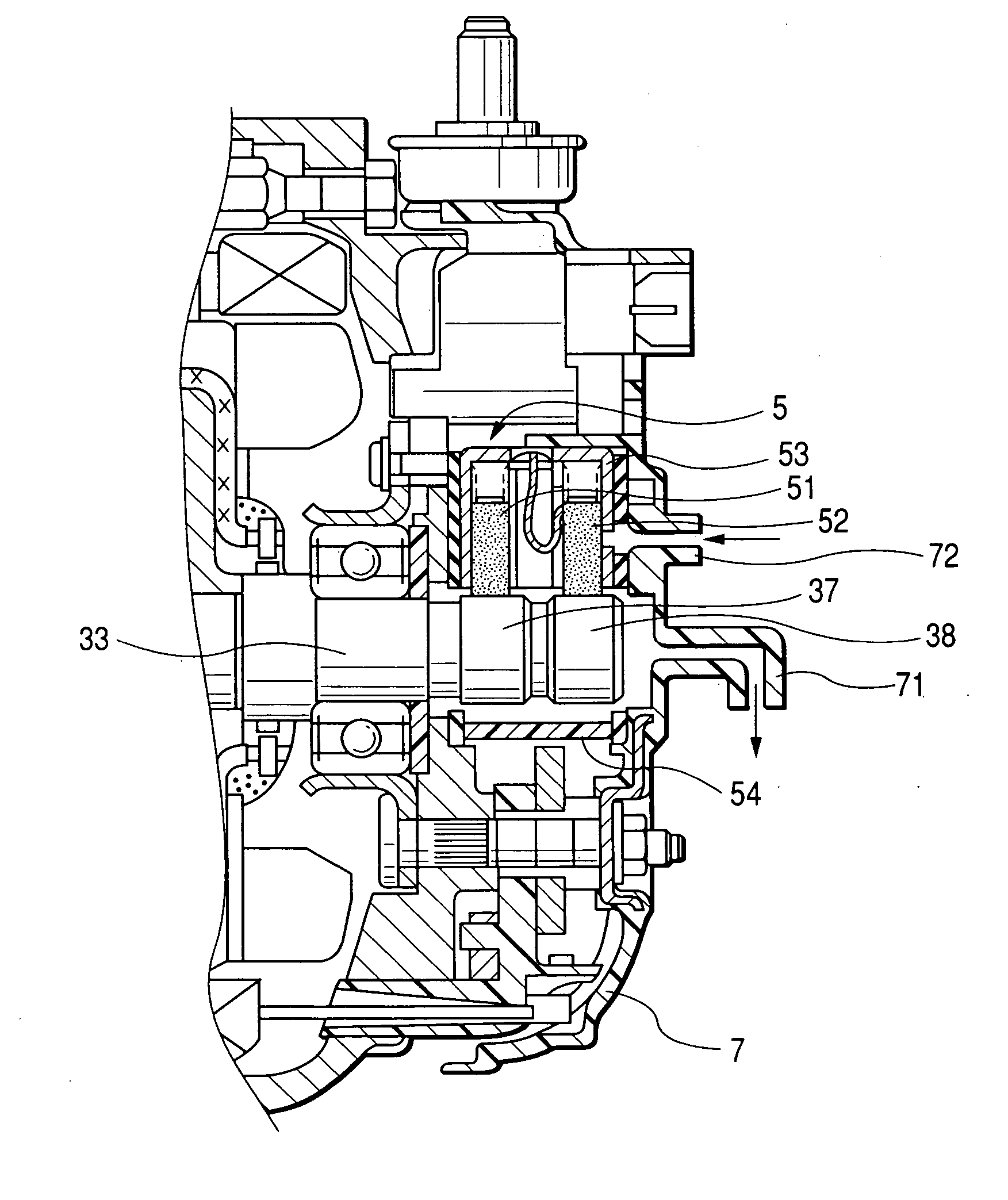
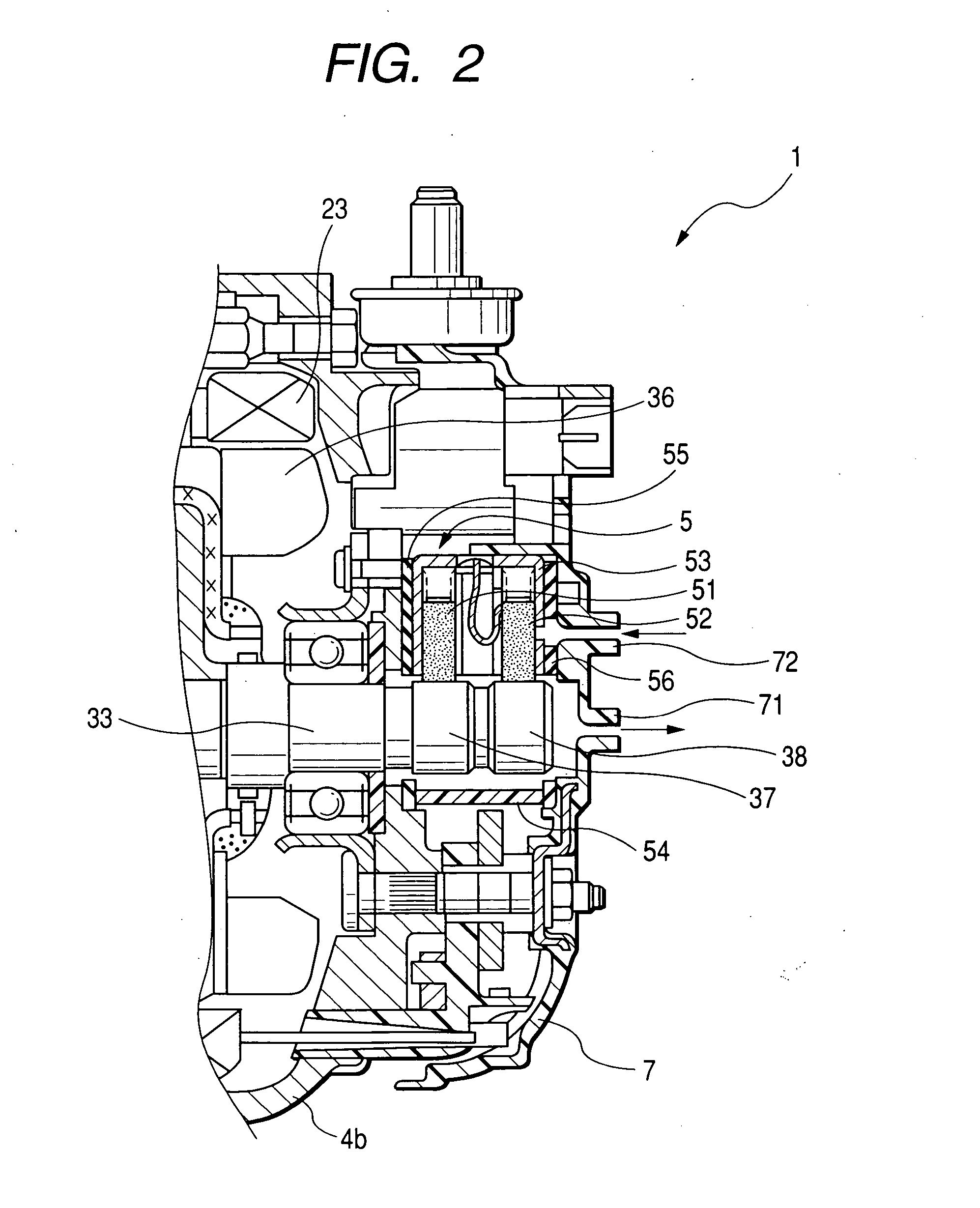
[0028]FIG. 1 shows a cross section of an on-vehicle alternator of the embodiment. FIG. 2 is an enlarged cross section of a principal part of an on-vehicle alternator of the embodiment. As shown in FIG. 1, an on-vehicle alternator 1 of the present embodiment includes a stator 2 around which an armature winding 23 is wound about, a rotor 3 which is disposed at an inner periphery of the stator 2 so as to face the stator 2, with a field winding 31 being wound thereabout, cooling fans 35 and 36 serving as cooling air generating means, each being fixed to each of axial end faces of the rotor 3 to generate cooling air as the rotor 3 rotates, a front-side housing 4a and a rear-side housing 4b for holding the stator 2 and the rotor 3, a brush apparatus 5 for supplying electric power to the field winding 31, a voltage ...


PUM


Abstract

An alternator (AC generator) to be mounted on a vehicle comprises slip rings, brushes, a brush holder, a rear cover, and sealing members. The slip rings are fixed on a rotary shaft and rotatable together with the rotary shaft. The brushes are slidable on the slip rings and the brush holder accommodates the brushes therein. The slip-ring cover covers the slip rings as well as the brush holder and the rear cover covers electronic components including the brushes. The sealing members give a sealing performance to an inner space containing slid portions of the brushes on the slip rings. The rear cover, the brush holder, and the sealing member have a ventilating passage for positively causing an flow of air from the inner space containing the slid portions of the brushes on the slip rings to an outside of the alternator.

Description

CROSS-REFERENCE TO RELATED APPLICATION [0001] This application is based on and claims the benefit of priority from earlier Japanese Patent Application No. 2005-160838 filed on Jun. 1, 2005, the description of which is incorporated herein by reference. BACKGROUND OF THE INVENTION [0002] 1. Technical Field of the Invention [0003] The present invention relates to an alternator (on-vehicle AC generator) which Is mounted on an engine installed in vehicles such as automobiles and trucks, and in particular, to an alternator equipped with a brush and slip ring structure to deliver the power. [0004] 2. Related Art [0005] Most engine-driven vehicles are generally equipped with alternators (on-vehicle AC generators), which generate power responsively to the rotation of the engines. Generally known conventional alternators are generally equipped with a rotary shaft and a pair of stator and rotor covered by a housing. The rotary shaft fixedly passes the rotator, so that both the rotary shaft and...

Claims


Application Information

Patent Timeline
Patent Type & Authority Applications(United States)
IPC IPC(8): H02K5/10H01R39/38H02K5/12
CPCH02K9/28H02K5/141
Inventor WADA, HITOSHIISHIDA, HIROSHI
Owner DENSO CORP
Why Eureka
Try Eureka