
Manipulator for positioning a test head, particularly at a tester

a technology for manipulators and test heads, applied in the field of manipulators, can solve the problem of only being able to adjust repeatedly with undue complication

Inactive Publication Date: 2006-12-07
HEIGL HUBERTUS
View PDF3 Cites 4 Cited by
  • Summary
  • Abstract
  • Description
  • Claims
  • Application Information

AI Technical Summary

Benefits of technology

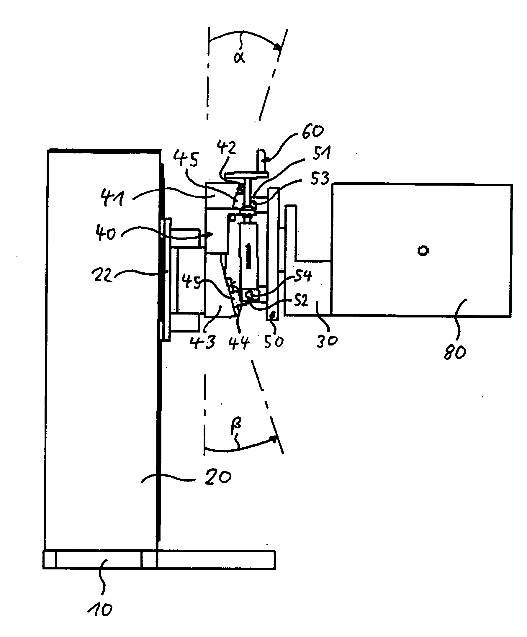
[0011] The manipulator in accordance with the invention is based on having discovered how to movably dispose the first supporting point such that the first supporting point can be moved between a starting position and an end position relative to the mount in overcoming a return force. In this way, the supporting point represents a movable supporting articulated link which now makes it possible to endow the plate with a certain compliance as compared to the mount. Despite this compliance due to the motion of the supporting point relative to the mount, precise adjustment of the test head is assured. The reason for this is that the supporting point is movable between a starting position and an end position in overcoming a return force. This return force thus counteracts motion of the supporting point relative to the mount.
[0015] It has been discovered to be particularly an advantage to dispose a linear guide for the first supporting point at the upper supporting surface and / or a linear guide for the second supporting point at the lower supporting surface. The linear guide ensures precisely motion of the supporting point relative to the mount. In addition, the linear guide has the advantage of absorbing any transverse forces and moments as may materialize.
[0016] Furthermore, the first supporting point may be provided with a supporting roller supported at the upper supporting surface, and / or the second supporting point with a supporting roller supported at the lower supporting surface. Although, unlike a linear guide, the supporting roller absorbs no transverse forces and moments it contributes towards relatively simple and cost-effective fabrication.
[0024] It is furthermore of advantage to secure the lead screw bearing to the mount in achieving a defined location of the lead screw and thus of the lead screw nut relative to the mount. When the upper supporting surface or the lower supporting surface does not extend in the axial direction of the lead screw, it has been discovered to be particularly expedient to dispose the lead screw bearing to pivot about an axis oriented orthoganal to the first axial direction of the lead screw at the mount. This ensures that the housing and thus the lead screw do not counteract motion of the supporting point.
[0025] For simple shifting of the lead screw nut in the axial direction of the lead screw the lead screw is expediently devised for being powered by a crank or a motor.

Problems solved by technology

Although the known manipulator, because of its combination of rotational motions of the pivot link and of the dual articulated links, features manifold adjustment capabilities horizontal, repeatable adjustment is only possible with undue complication.

Method used


Image

  • Manipulator for positioning a test head, particularly at a tester
  • Manipulator for positioning a test head, particularly at a tester
  • Manipulator for positioning a test head, particularly at a tester

Examples


Embodiment Construction

[0039] Referring now to FIG. 1 there is illustrated the manipulator serving to position a test head 80 to a tester (not shown) for eleconic components, such as, for example, integrated circuits or wafers. For this purpose, the manipulator comprises a cradle 30 to which the test head 80 is secured. In addition, the manipulator features positioning means connected to the cradle 30 and which, among other things, comprise a column 20 extending vertical and a vertical carriage 22. The vertical carriage 22 can be linearly moved vertical on two guide rails 21 located parallel to each other, disposed on the column 20 and for this purpose may be powered by drive means. By means of a locking lever the vertical carriage 22 can be locked in a predefined position on the column 20. In addition, further positioning means may be provided on the vertical carriage 22, for instance a horizontal carriage or articulated links pivot mounted in a horizontal plane, known as pivot links from DE 101 32 489 A...


PUM


Abstract

A manipulator for positioning a test head, particularly at a tester is provided with positioning means for positioning the test head three-dimensionally and forming a mount. The manipulator comprises furthermore a cradle to which the test head can be secured and which is connected to the positioning means. The cradle is connected to a plate comprising at least one first supporting point. The plate is pivotally mounted at the first supporting point about a first axis. To achieve, on the one hand, precise adjustment and, on the other, a certain compliance, the first supporting point is movable between a starting position and an end position relative to the mount in overcoming the effect of a return force.

Description

CROSS REFERENCE TO RELATED APPLICATION [0001] This application claims the priority of German Patent Application No. 10 2005 019 564.4 filed on 27 Apr. 2005, herein incorporated by reference. FIELD OF THE INVENTION [0002] The invention relates to a manipulator, serving particularly to position a test head at a tester. The manipulator is provided with a positioning means for positioning the test head three-dimensionally and which forms a mount. In addition, the manipulator is provided with a cradle connected to the positioning means and to which the test head is securable. The cradle is connected to a plate comprising at least one first supporting point. The plate is mounted to pivot about a first axis at the first supporting point. BACKGROUND OF THE INVENTION [0003] The manipulator for positioning a test head normally has a plurality of translational and rotational degrees of freedom in thus being suitable for precisely positioning the test head three-dimensionally. This is why, as a...

Claims


Application Information

Patent Timeline
Patent Type & Authority Applications(United States)
IPC IPC(8): B66F9/06
CPCF16M11/10F16M11/12G01R31/2887F16M11/2014F16M11/18
Inventor HEIGL, HUBERTUS
Owner HEIGL HUBERTUS
Learn More