
Intelligent traffic management system for networks and intelligent traffic management method using the same

a traffic management system and intelligent technology, applied in the field of intelligent traffic management system for networks and intelligent traffic management method using intelligent traffic management system, can solve the problems of excessive maintenance costs, reduced efficiency, and reduced user experience, and achieve the effect of reducing expenses

Inactive Publication Date: 2006-11-30
NITGEN TECH
View PDF7 Cites 48 Cited by
  • Summary
  • Abstract
  • Description
  • Claims
  • Application Information

AI Technical Summary

Benefits of technology

"The present invention provides an intelligent traffic management system for networks and an intelligent traffic management method using the system. The system includes a plurality of Global Load Balance (GLB) agents and a plurality of Server Load Balance (SLB) agents. The GLB agents calculate the hops and packet Internet groper response time between a user Terminal and a POP (Point of Presence) to select an optimal POP for the user. The SLB agents collect server load balancing information and system resource information of service servers. The system management server controls and manages POPs distributed over a wide area, and allows information about system resources and the number of sessions for each port to be transmitted through a control of operation of the GLB and SLB agents. The user terminal includes a Domain Name Server (DNS) for automatically transmitting IP address information of the traffic management server when requested by the user. The system reduces expenses by not requiring a separate system for managing traffic."

Problems solved by technology

In the case where such an enormous number of servers are managed by a single Internet data center, a problem arises in that all visitors having registered at a portal site cannot access the portal site when it is not possible to operate the Internet data center due to an internal cause associated with hardware or software, and an external cause such as a power failure.
If, in the case of a small-sized web site operated by a small number of servers, for example, three or four servers, servers are managed in various areas, like a large-sized portal site, excessive maintenance costs are incurred.
Accordingly, in the case where the rate of use of system resources, such as the CPU and memory of the connected service server, is high or the number of sessions for each port is large, considerable display delay occurs in the output of web pages operated by the selected service server.
Furthermore, in the case where the connected service server has a hardware or software defect, the user terminal cannot be connected to the selected service server so that the user cannot view the web pages, and the user should request connection to the service server having been requested by the user again.
These problems become serious for portal sites having a large number of regular visitors.
As a result, the conventional load distribution scheme based on the round robin method is disadvantageous in that it cannot provide a high quality service and no connection may be provided to the user because server condition information about the congestion of traffic, increases in the load of the CPU and memory and hardware defects cannot be foreseen.
Furthermore, the conventional load distribution scheme is disadvantageous in that the construction costs of a system are additionally required due to an increase in the number of servers resulting from an increase in simultaneous traffic for multimedia content-oriented Internet services.
Accordingly, the L4 is problematic in that it cannot perform the server load balancing function of controlling the user terminal to be connected to an actually optimal service server.
Furthermore, since the L4 is a hardware device, overload occurs when the number of packets requesting connection to service servers is increased, so that the L4 acts as a bottleneck, thus rapidly deteriorating QoS.
Accordingly, since the number of L4s must be increased whenever the number of service servers is increased, the construction of additional systems and great expenses due to this system construction are incurred.

Method used


Image

  • Intelligent traffic management system for networks and intelligent traffic management method using the same
  • Intelligent traffic management system for networks and intelligent traffic management method using the same
  • Intelligent traffic management system for networks and intelligent traffic management method using the same

Examples


Embodiment Construction

[0058] A preferred embodiment of the present invention is described with reference to the accompanying drawings hereinafter. In the drawings, the same reference numerals are used throughout the different drawings to designate the same or similar components.

[0059]FIG. 2 is a system configuration diagram of an intelligent traffic management system according to the present invention. FIG. 3 is a detailed block diagram of a traffic management server of FIG. 2.

[0060] The intelligent traffic management system of the present invention includes a plurality of Global Load Balance (GLB) agents 33, a plurality of Server Load Balance (SLB) agents 32, an Internet traffic management server, and a user terminal 1′.

[0061] The plurality of GLB agents 33 are each provided in a GLB agent dedicated server 31′ located in each POP 30 to generate global load balancing information obtained by calculating a hop and packet Internet groper response time between the user terminal 1′ and the POP 30 using the...


PUM


Abstract

Disclosed herein is an intelligent traffic management system and an intelligent traffic management method using the intelligent traffic management system. The intelligent traffic management system includes a plurality of Global Load Balance (GLB) agents, a plurality of Server Load Balance (SLB) agents, an Internet traffic management server, and a user terminal. The GLB agents are each provided in a GLB agent dedicated server located in each Point Of Presence (POP) to generate global load balancing information. The SLB agents are each provided in a service server located in the POP to collect server load balancing information at regular intervals. The Internet traffic management server controls and manages POPs distributed over a wide area, and searches for an optimal POP and an optimal service server. The user terminal includes a domain Database (DB) and a client agent program.

Description

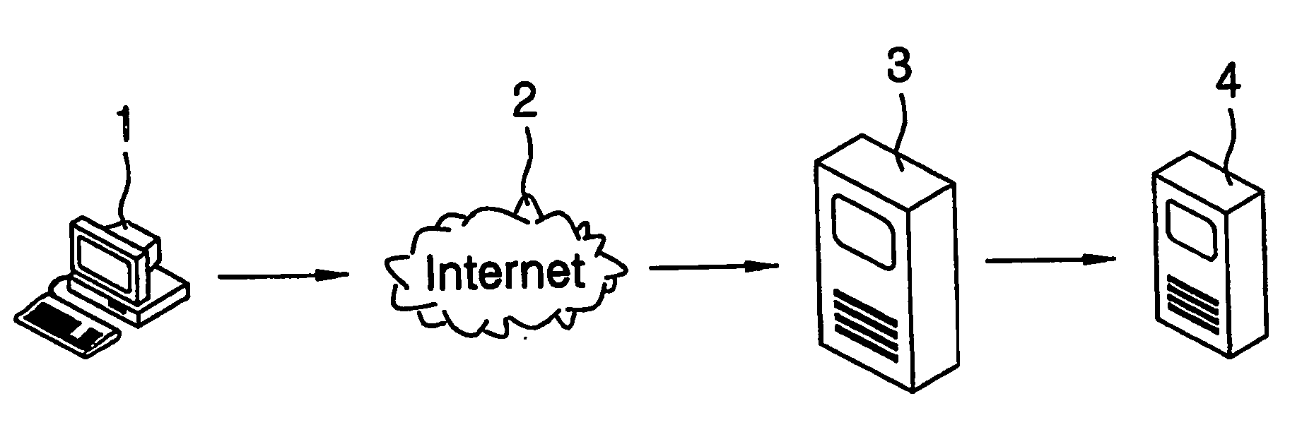
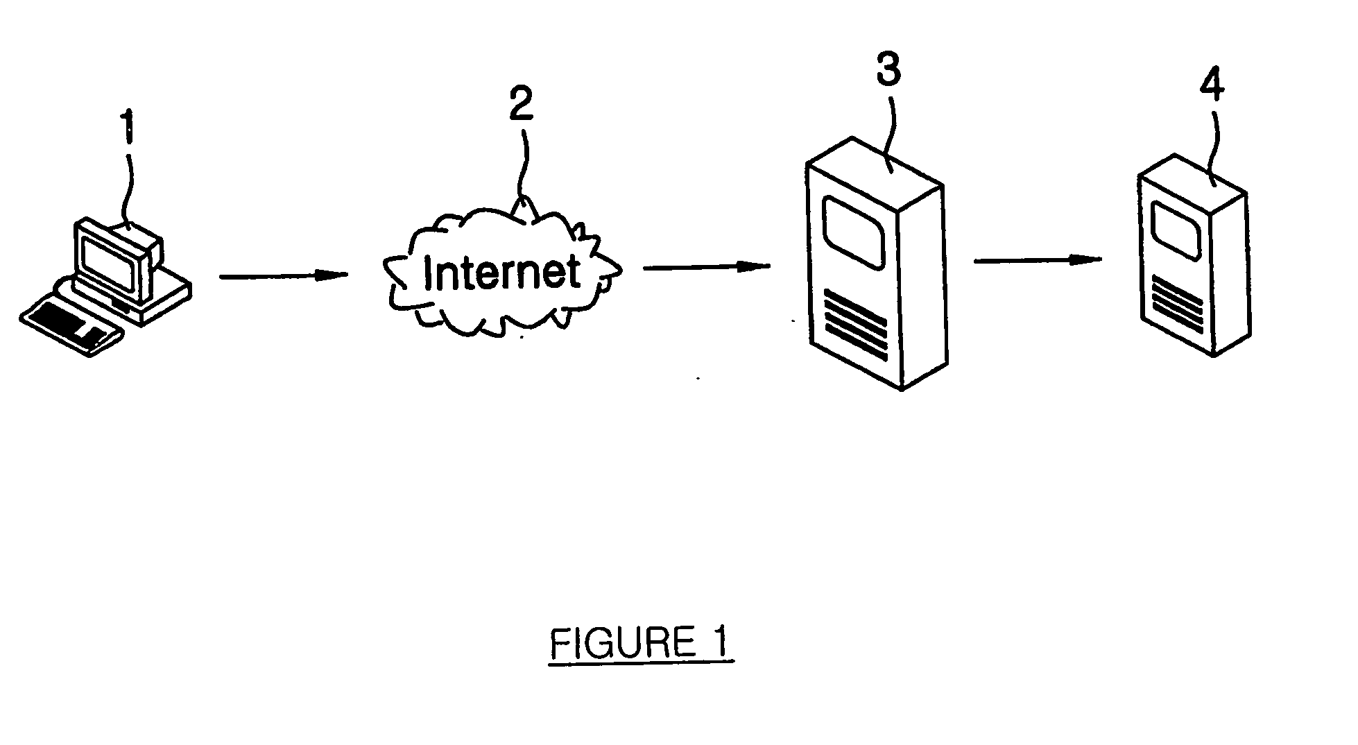
TECHNICAL FIELD [0001] The present invention relates generally to an intelligent traffic management system for networks and an intelligent traffic management method using the intelligent traffic management system. In particularly, the present invention relates to an intelligent traffic management system for networks and an intelligent traffic management method using the intelligent traffic management system, which select one service server having an optimal connection path to a user from service servers located in a plurality of Internet data centers requested by the user and control a user terminal to be connected to the selected service server. BACKGROUND ART [0002]FIG. 1 is a schematic configuration diagram of a conventional system required to assign a connection path between a user terminal and a service server through a domain name server. [0003] As shown in the drawing, the system includes a user terminal 1 to request connection to a specific server using domain name informati...

Claims


Application Information

Patent Timeline
Patent Type & Authority Applications(United States)
IPC IPC(8): G06F15/173G06F13/00G06F17/00H04L45/80
CPCH04L67/1008H04L67/1002H04L67/125H04L67/1001G06Q50/00
Inventor YOON, KIJOOLEE, NAMYEOL
Owner NITGEN TECH
Learn More