
KVM switch and a computer switching method

a computer and switch technology, applied in the field of kvm switches, can solve the problems of reducing wasting money on equipment, occupying too much space, etc., and achieve the effect of increasing the compatibility of the console module and reducing the cos

Active Publication Date: 2006-11-23
ATEN INT CO
View PDF19 Cites 17 Cited by
  • Summary
  • Abstract
  • Description
  • Claims
  • Application Information

AI Technical Summary

Benefits of technology

[0009] It is therefore an aspect of the present invention to provide a KVM switch, which decreases the cost and increases the compatibility of the console modules thereof.
[0014] It is another aspect of the present invention to provide a computer switching method, which operates a KVM switch as a terminal system, for reducing the design difficulty and saving time and effort necessary for upgrading the KVM switch.
[0017] It is still another aspect of the present invention to provide a computer switching method, of which most processing of the OSD image relies on a remote processor rather than a console processor, to expand the functions and to enhance the compatibility of the console module.
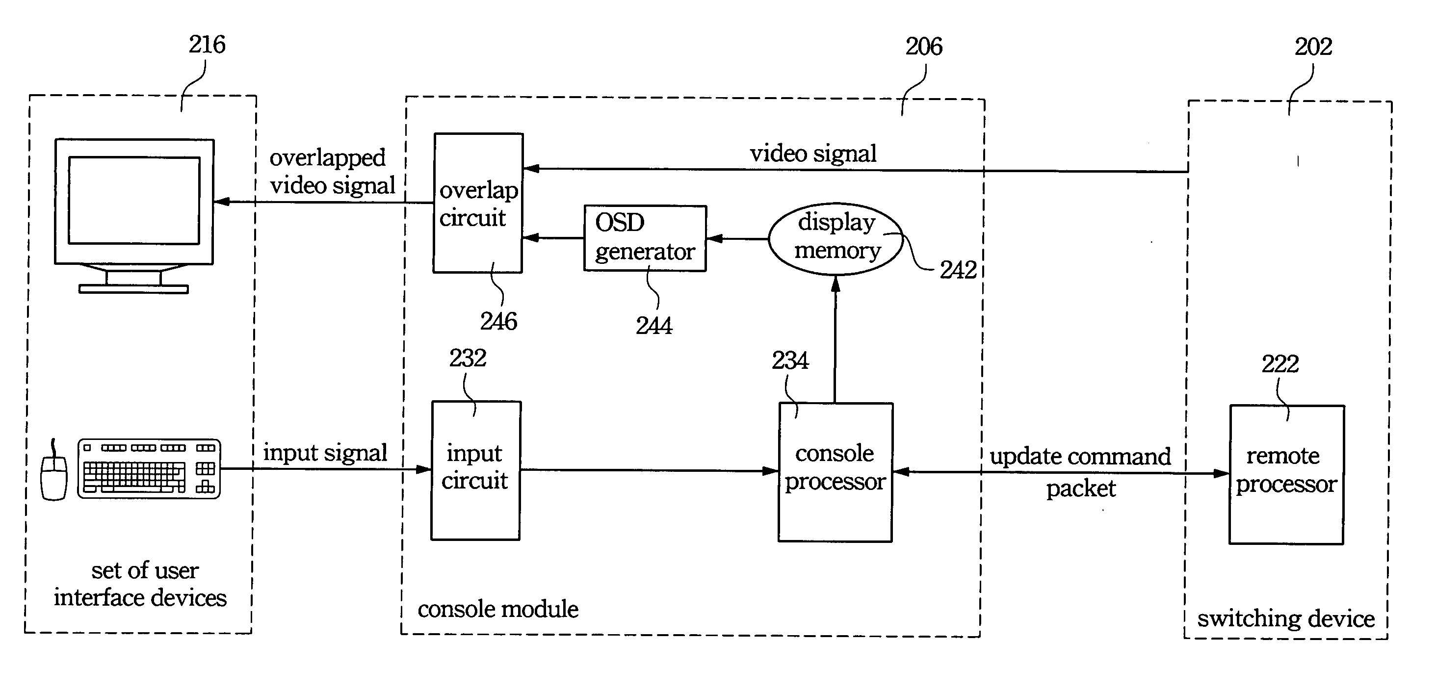
[0020] Accordingly, the cost of the console module can be decreased because it omits a very fast processor and many expensive memories. The design difficulty of the console module can also be reduced due to not requiring complicated memory management techniques. Moreover, the upgrade procedure, which is applied only to the switching device, is simplified, and thus time and effort for upgrading the KVM switch are substantially saved.

Problems solved by technology

However, this equipment wastes money and occupies too much space if one has several computers.
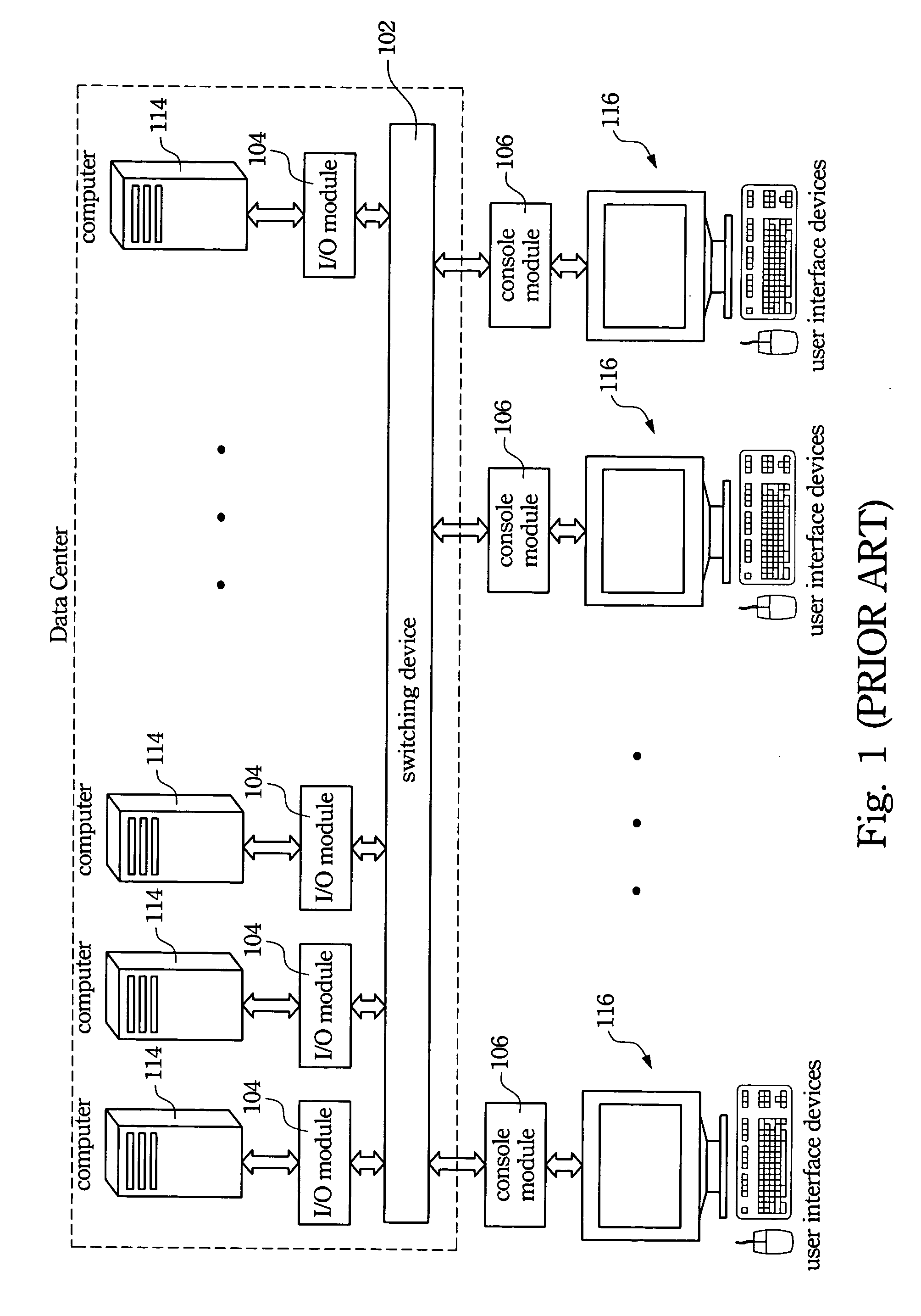
However, the traditional configuration of the KVM switch seems to give a limited system, in which all necessary information possibly used in the OSD image must have been saved before deciding what is to be displayed, and thus the traditional configuration limits the functions and reduces the compatibility of the console module 106.
Moreover, if the necessary information is too large to be saved in one console module 106, some memory management techniques may be applied or expensive memories may be added, incurring added costs and design difficulty.
In addition, if the firmware needs to be upgraded, every console module 106 has to be individually upgraded because each responds only to its own OSD, and the upgrade procedure certainly takes time and waste effort.

Method used


Image

  • KVM switch and a computer switching method
  • KVM switch and a computer switching method
  • KVM switch and a computer switching method

Examples


Embodiment Construction

[0029] Reference will now be made in detail to the present preferred embodiments of the invention, examples of which are illustrated in the accompanying drawings. Wherever possible, the same reference numbers are used in the drawings and the description to refer to the same or like parts.

[0030] The present invention operates a KVM switch as a terminal system. The terminal system relies on a remote processor instead of a console processor for processing content of an OSD image, and thus decreases the cost and increases the compatibility of the console modules. The design difficulty is also reduced, and time and efforts for upgrading the KVM switch are saved.

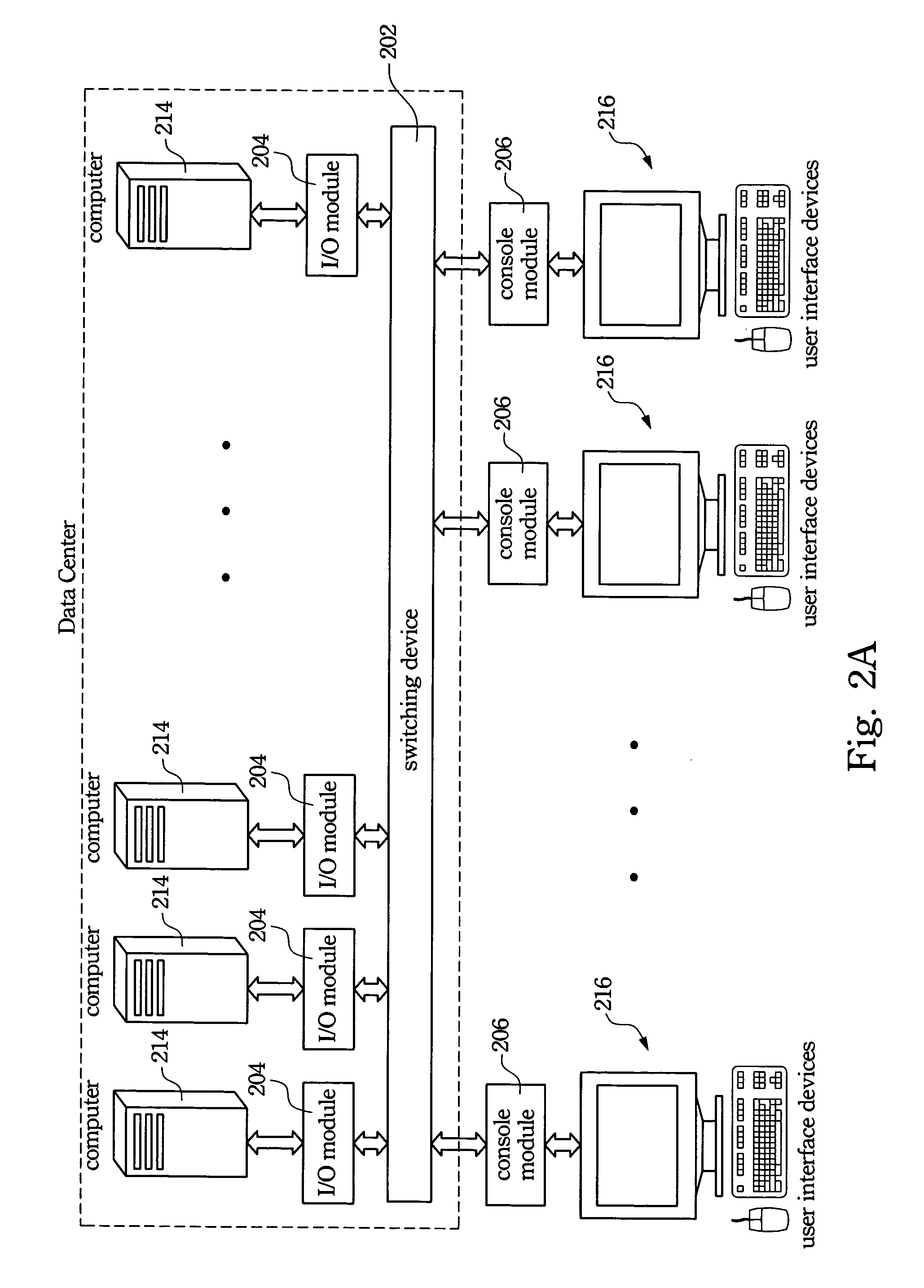
[0031]FIG. 2A is a schematic view depicting a KVM switch of one preferred embodiment of the present invention, for illustrating connections between the KVM switch, computers, and sets of user interface devices. Each of the computers 214 is connected to a switching device 202 through a respective I / O module 204 thereof, and each ...


PUM


Abstract

An input signal from the set of user interface devices is captured, and the input signal is converted into a packet by a console processor. The packet is transferred to a remote processor, and the remote processor generates an update command according to the packet. The update command is transferred to the console processor, and an OSD image is generated according to the update command. The OSD image is overlapped onto a video signal from the computers, and the overlapped video signal is output to the set of the user interface device.

Description

BACKGROUND [0001] 1. Field of Invention [0002] The present invention relates to a KVM switch. More particularly, the present invention relates to a KVM switch operated as a terminal system. [0003] 2. Description of Related Art [0004] With the rapid development in information technology, computers and their peripherals have become very popular. Typically, each computer is equipped with one set of user interface devices, and may including a keyboard, a mouse and a monitor. However, this equipment wastes money and occupies too much space if one has several computers. Therefore, a keyboard-video-mouse (KVM) switch is proposed to use at least one set of user interface devices to manage several computers and their peripherals. Using the KVM switch reduces hardware costs and decreases waste of space while simultaneously conquering the problem of compatibility between different interfaces. [0005]FIG. 1 is a schematic view depicting a traditional KVM switch. Each of computers 114 is connecte...

Claims


Application Information

Patent Timeline
Patent Type & Authority Applications(United States)
IPC IPC(8): G09G5/00
CPCG06F3/023G09G2370/24G06F3/14
Inventor ZHANG, JIN-YU
Owner ATEN INT CO
Learn More