
Staircase finishing plate arrangement

a technology for finishing plates and staircases, applied in the direction of floors, floors, building constructions, etc., can solve the problems of weaker strength of nosing, prone to shear off, and relatively thin layer, so as to improve the integrity of the nosing, reduce the risk of damage or breakage, and ensure the effect of stability

Inactive Publication Date: 2006-11-23
GRENIER GILLES
View PDF18 Cites 14 Cited by
  • Summary
  • Abstract
  • Description
  • Claims
  • Application Information

AI Technical Summary

Benefits of technology

"The present invention provides an improved staircase finishing plate arrangement that is stronger and more stable than conventional arrangements. The arrangement includes a tread portion with a finishing surface layer, a nosing that extends across the tread, and a supporting layer that is affixed to the tread's surface and mortised into the nosing. The arrangement also includes securement means for aligning and securing the finishing plate to the tread. The invention allows for a more consistent construction and continuous or substantially continuous abutment and / or securing of the finishing plate to the tread. The arrangement provides greater integrity, resistance to damage or breakage, and better support for the finishing plate. The invention also includes a staircase including the finishing plate arrangement."

Problems solved by technology

The prior art proposals suffer from the disadvantage that the facing layer tends to be of relatively thin gauge when compared to the thickness of a conventional tread and accordingly is weaker in strength than the nosing which is of stouter dimension.
The result is that during normal use of the staircase the nosing tends to shear off with concomitant wastage of time, materials and the unpleasantness of the situation.
A further disadvantage of these proposals is that it is seldom possible to obtain a proper and consistent abutment with the subjacent vertical riser.
A less than satisfactory result is achieved.

Method used


Image

  • Staircase finishing plate arrangement
  • Staircase finishing plate arrangement
  • Staircase finishing plate arrangement

Examples


Embodiment Construction

[0025] With reference to the annexed drawings the preferred embodiments of the present invention will be herein described for indicative purpose and by no means as of limitation.

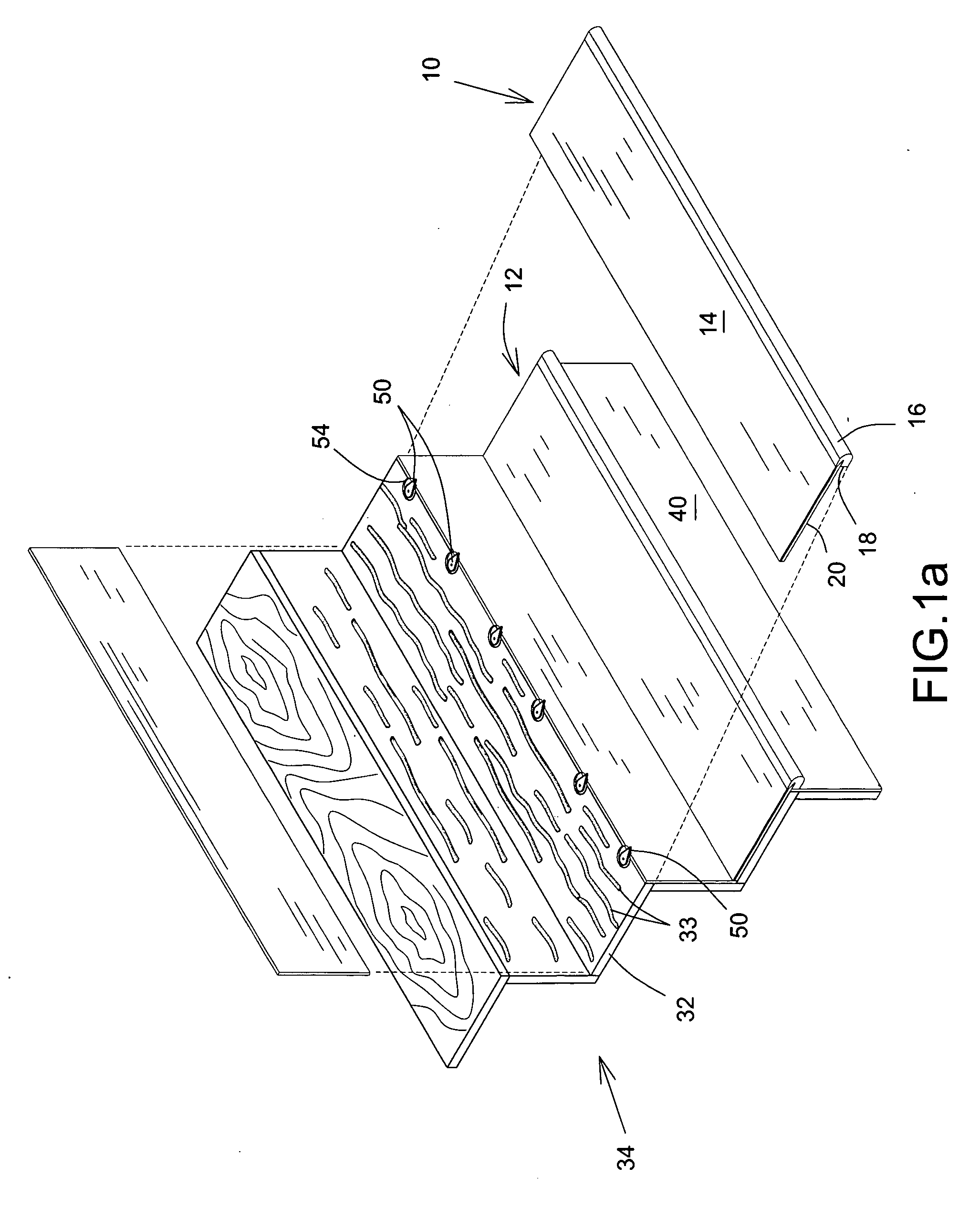
[0026] Referring first to FIGS. 1 and 2, there is shown a staircase finishing plate arrangement 10 comprising a tread portion 12 presenting an upper surface layer 14 with a nosing 16 extending along the full length of the plate (across the staircase), the nosing having a vertical abutment wall 18.

[0027] A support layer 20 is provided beneath the surface layer 14 and is bonded to the underside thereof. The support layer 20 has a feathered-edge 22 mortised into a correspondingly tapered groove 24 formed in the nosing 16 as shown, thus affording a positive, stable and substantially tight interengagement of the two layers and the nosing to provide integrity and a degree of rigidity. Typically the thickness of the support layer may be about ¼ inch with that of the surface layer being about ⅛ inch, for a total o...


PUM


Abstract

A staircase finishing arrangement includes a tread portion presenting a finishing surface layer, a nosing extending across substantially the whole length of the tread portion with a supporting layer affixed to the underside of the surface layer and mortised into the nosing, in the front and / or free side edges of the tread. Mechanical securement means are provided for interengagement as between the nosing and the subjacent riser, and are pivotally mounted such that upon interengagement limited adjustment may be achieved to secure the arrangement in proper transverse locational relationship with the stair.

Description

FIELD OF THE INVENTION [0001] The present invention concerns a staircase finishing plate arrangement for installation on a non-finished tread or use as a replacement for a worn tread. BACKGROUND OF THE INVENTION [0002] It is well known in the art to provide a finishing capping for an unfinished tread, as a replacement of a removed staircase carpet or as a repair element in the replacement of a worn-out tread. An example of such a capping is described in U.S. Pat. No. 4,783,939 and includes a nosing at one end of a capping plate with an insert bonded to the underside of the capping plate. A further example is shown in U.S. Pat. No. 6,067,758 in which a stair construction element for renovation of a worn tread includes a tread portion provided with a nosing at a front margin thereof. My earlier U.S. Pat. No. 6,397,529 discloses a tread finishing plate comprising a top exposed layer of hardwood with a thin internal layer of a veneer bonded or laminated to the underside of the top layer...

Claims


Application Information

Patent Timeline
Patent Type & Authority Applications(United States)
IPC IPC(8): E04F11/00
CPCE04F11/16
Inventor GRENIER, GILLES
Owner GRENIER GILLES
Learn More