
Artificial knee with cushion function

a technology of artificial knees and cushion functions, applied in the field of artificial knees, can solve the problems of not being able to comfortably walk the amputee wearing the artificial knee, the cushion mechanism inside the artificial knees is not adjustable to adapt to different situations of the user, and the artificial knee can only imitate a bending or rotation function, so as to ensure the safety of the user

Inactive Publication Date: 2006-11-16
CHANG YU MECHANICAL SYST
View PDF1 Cites 59 Cited by
  • Summary
  • Abstract
  • Description
  • Claims
  • Application Information

AI Technical Summary

Benefits of technology

[0006] The primary objective of the present invention is to provide an improved artificial knee that is able to allow the user to bend and provide safety to the user when the body weight of the user is on top of the artificial knee within a predetermined angle.
[0007] Another objective of the present invention is to provide a pneumatic cylinder inside the artificial knee. The cushion of the pneumatic cylinder is able to provide a damping effect to the user and is adjustable so that the user is able to change the damping effect to adapt to different situations.
[0010] Still, another objective of the present invention is that the cylinder also has multiple adjusting portions received in the cover to adjust airflow flux flowing between a top chamber and a bottom chamber inside the cylinder such that the user is able to adjust the cushion of the cylinder.

Problems solved by technology

That is the currently available artificial knee can only imitate a bending or rotation function of a natural knee without the consideration of bearing the body weight within a certain rotation angle of the artificial knee.
Therefore, the amputee wearing the artificial knee is not able to walk comfortably due to a lack of cushion function.
Although there are patents disclosing artificial knees with cushion function to provide the user better conditions to wear the artificial knee, the cushion mechanism inside these artificial knees is not adjustable to adapt to different situations the user is expected to confront.

Method used


Image

  • Artificial knee with cushion function
  • Artificial knee with cushion function
  • Artificial knee with cushion function

Examples


Embodiment Construction

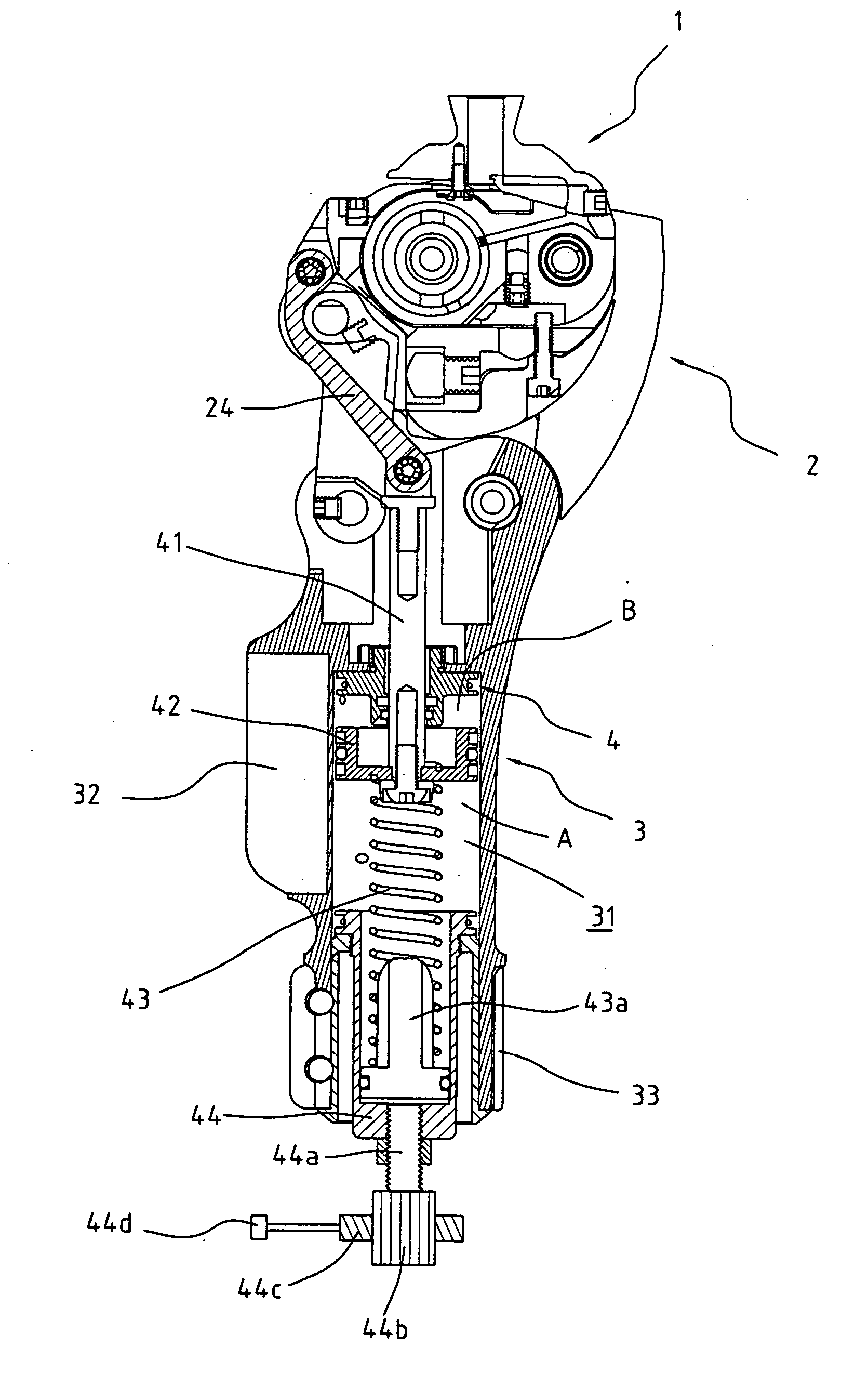
[0023] With reference to FIG. 1, it is noted that the artificial knee in accordance with the present invention includes a supporting portion 1, a knee portion 2, a leg portion 3, and a pneumatic cylinder 4.

[0024] With reference to FIGS. 1, 2, 2A and 3, it is noted that the supporting portion 1 is mounted on top of the knee portion 2 for connection to a user's thigh. The knee portion 2 is provided with a saddle-like body 21, a front knee 22, and a rear knee 23 opposite to the front knee 22. The saddle-like body 21 is pivotally and respectively connected to a respective top of the front knee 22 and the rear knee 23. A respective bottom of the front knee 22 and the rear knee 23 is pivotally connected to the leg portion 3 so as to form a four-link-rod mechanism imitating the human knee operational track. A supporting rod 24 is pivotally connected to the supporting portion 1. However, in different embodiment, the supporting rod 24 may be pivotally connected to either the front knee 22 o...


PUM


Abstract

An artificial knee has a supporting portion, a knee portion, and a leg portion. The knee portion has a saddle-like body, a front knee pivotally connected to the saddle-like body and a rear knee. The leg portion has a pneumatic cylinder received in the receiving space in the leg portion. Pivotal movement of the saddle-like body relative to the front knee is able to activate the pneumatic cylinder to provide a cushion effect to a load on top of the supporting portion.

Description

BACKGROUND OF THE INVENTION [0001] 1. Field of the Invention [0002] The present invention relates to an artificial knee, and more particularly to an artificial knee with cushion function so that the user of the artificial knee is able to comfortably wear the artificial knee. [0003] 2. Description of Related Art [0004] Artificial knee is aimed to provide the amputee a function with which the user is able to comfortably walk with an artificial leg. That is the currently available artificial knee can only imitate a bending or rotation function of a natural knee without the consideration of bearing the body weight within a certain rotation angle of the artificial knee. Therefore, the amputee wearing the artificial knee is not able to walk comfortably due to a lack of cushion function. Although there are patents disclosing artificial knees with cushion function to provide the user better conditions to wear the artificial knee, the cushion mechanism inside these artificial knees is not ad...

Claims


Application Information

Patent Timeline
Patent Type & Authority Applications(United States)
IPC IPC(8): A61F2/64A61F2/74
CPCA61F2/644A61F2002/5003A61F2002/5007A61F2002/5009A61F2002/748A61F2002/5072A61F2002/6818A61F2002/747A61F2002/5035A61F2/74A61F2/748
Inventor HARN, CHUEN-SENZHEN, RUENG-JIE
Owner CHANG YU MECHANICAL SYST
Learn More