Imaging operation controller

a technology of operation controller and function indicator, which is applied in the field of image operation controller, can solve the problems of difficult recognition of function indicators on the control panel when necessary, and the inability of function indicators printed with luminous paint to improve the operability of the control panel, and achieve the effect of improving the operability

Inactive Publication Date: 2006-11-16
SONY CORP
View PDF14 Cites 13 Cited by
  • Summary
  • Abstract
  • Description
  • Claims
  • Application Information

AI Technical Summary

Benefits of technology

[0011] The present invention has been made in view of such a problem and it is therefore desirable to provide an imaging operation controller provided with function indicators capable of ensuring the visual recognition thereof even in a dark photographing environment and of contributing to the improvement of the operability of the imaging operation controller.
[0013] According to the embodiment of the present invention, when the business camera is used in a dark environment for taking an image of a scene in a studio or on a stage or for taking a night scenery, the function indicators can be lighted by the plurality of indicator lighting light sources. Consequently, the user is easily able to recognize the illuminated function indicators visually and is able to operate the desired operating members correctly without making a mistake. Thus the imaging operation controller of the present invention has improved operability.

Problems solved by technology

Therefore, it is difficult to recognize the function indicators on the control panel when necessary while the camera is used for a long time in a dark environment even though the characters of the function indicators are printed with a luminous paint.
Thus the function indicators printed with a luminous paint cannot improve the operability of the control panel.

Method used


Image

  • Imaging operation controller
  • Imaging operation controller
  • Imaging operation controller

Examples


first embodiment

[0077] A control panel 60 will be described with reference to FIGS. 15 to 19 and 21.

[0078]FIG. 15 is an exploded perspective view of the control panel 60 included in an imaging operation controller embodying the present invention, FIG. 16(A) is a plan view of a base plate 66 included in the control panel 60, FIG. 16(B) is a side elevation of the base plate 66 taken in the direction of the arrow B in FIG. 16(A), FIG. 17 is a sectional view of a printed indicator sheet and FIG. 18 is a view of assistance in explaining steps of making the printed indicator sheet.

[0079] Referring to FIG. 22, the control panel 60 is attached to a back part 36 of a casing 30. The control panel 60 is provided with a plurality of operating members 62 for operating the imaging operation controller 20, and function indicators 64 indicating the functions of the operating members 62. The function indicators 64 are marked at positions near the operating members 62, respectively.

[0080] As show in FIG. 20, guar...

second embodiment

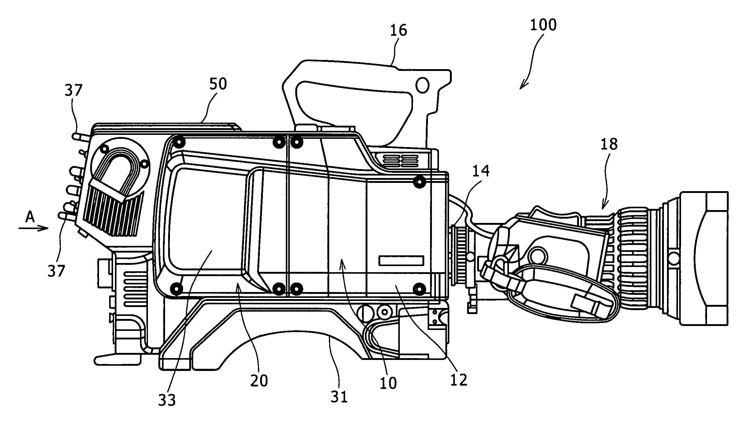
[0144] Referring to FIGS. 24 and 25, an imaging operation controller 20 in a second embodiment according to the present invention includes a casing 30, electronic devices held in the casing 30 and a cover 50. In this specification, the terms “right” and “left” are used to specify things and positions on the right and the left side of the imaging operation controller 20 as viewed from behind the imaging operation controller 20.

[0145] The casing 30 includes a frame 32 having a height, namely, a vertical dimension, a length, namely, a longitudinal dimension, and a width, namely, a lateral dimension, and covering members 33 attached to the frame 32.

[0146] A shoulder guard 31 is extended along the lower walls of the casing 14 of a camera unit 10 and the lower wall of the casing 30 of the imaging operation controller 20. The shoulder guard 31 defines an upward convex recess for receiving the user's shoulder (FIGS. 20 and 21).

[0147] As shown in FIG. 27, the frame 32 has a front part 34,...

third embodiment

[0204] An imaging operation controller in a third embodiment according to the present invention will be described in comparison with a known imaging operation controller.

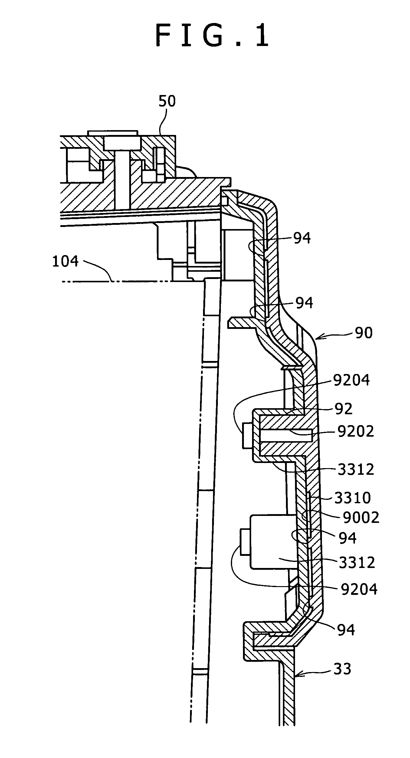
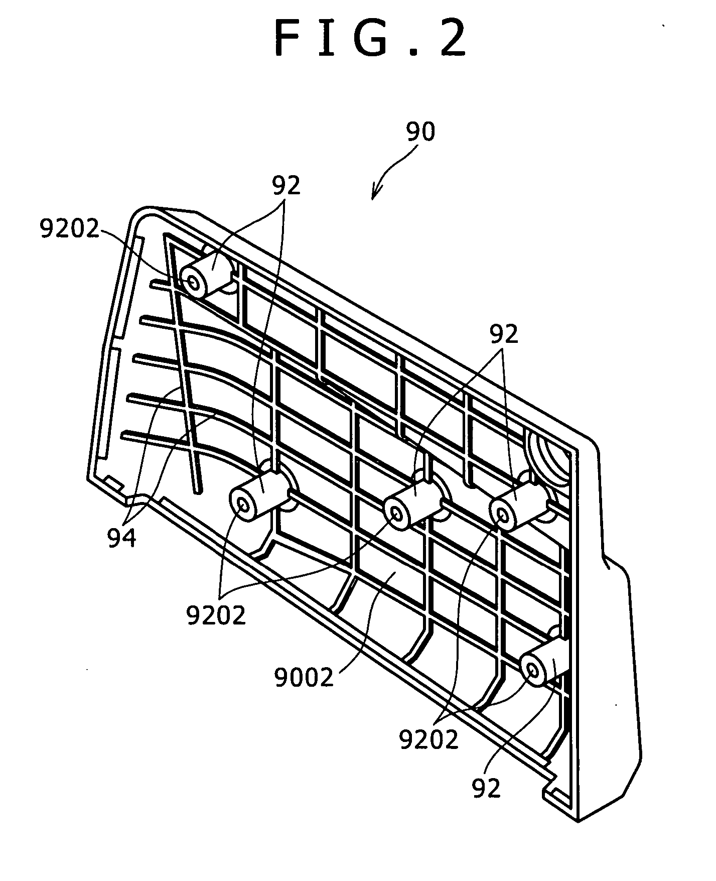
[0205] A camera, particularly, a business camera formed by uniting together a camera unit and a VTR unit, has a casing provided with ventilation passages through which air heated by a power circuit held in the casing is discharged outside.

[0206] When the camera is used on a rainy day or in an environment where the camera is likely to be splashed with water drops, such as a place near a swimming pool, it is likely that water drops enter the casing through the ventilation passages and cause electric parts to malfunction.

[0207] A previously proposed camera designed to avoid such a trouble has a casing provided with ventilation passages and covers made of a shape memory alloy and covering the ventilation passages. When the temperature in the casing rises, the covers curve so as to open the ventilation passages to dis...


PUM


Abstract

An imaging operation controller includes: a casing, a control panel attached to a back part of the casing and provided with a plurality of operating members and function indicators indicating the functions of the operating members and placed near the operating members, respectively. The control panel includes a base plate attached to the casing, a mounting plate placed on the base plate and a printed indicator sheet placed on the mounting plate. The plurality of operating members are supported on the base plate, indicator lighting light sources are supported on the base plate at positions respectively corresponding to the function indicators so as to emit light backward. The indicator lighting light sources are white light-emitting diodes attached to the base plate so as to emit light backward.

Description

CROSS REFERENCES TO RELATED APPLICATIONS [0001] The present invention contains subject matter related to Japanese Patent Application Nos. 2005-116634, 2005-116819, and 2005-117051 filed in the Japanese Patent Office on Apr. 14, 2005, the entire contents of which being incorporated herein by reference. BACKGROUND OF THE INVENTION [0002] 1. Field of the Invention [0003] The present invention relates to an imaging operation controller for converting image signals provided by a camera unit into video signals. [0004] 2. Description of the Related Art [0005] A previously proposed camera, such as a business camera for business use by a professional cameraman in a broadcasting station, includes a camera unit for generating image signals representing an image of an object and an imaging operation controller for converting image signals into corresponding electric signals and sending the electric signals to an external camera controller. The camera unit and the imaging operation controller ar...

Claims


Application Information

Patent Timeline
Patent Type & Authority Applications(United States)
IPC IPC(8): H04N5/225H04N23/75
CPCH04N5/2251H04N23/50H04N23/62H04N23/55H04N23/00
Inventor MAEDA, KAZUYOSHI
Owner SONY CORP
Why Eureka
Try Eureka