
Power toothbrush

a toothbrush and power technology, applied in the field of toothbrushes, can solve the problems of reducing the reliability of cost ore, easy design manufacturing, etc., and achieve the effect of reliable service and easy manufacturing

Inactive Publication Date: 2006-11-16
THE GILLETTE CO
View PDF99 Cites 52 Cited by
  • Summary
  • Abstract
  • Description
  • Claims
  • Application Information

AI Technical Summary

Benefits of technology

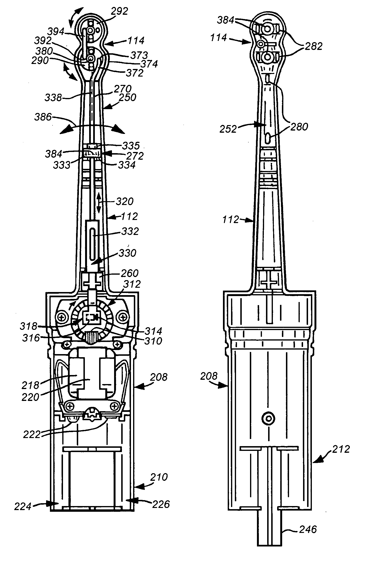
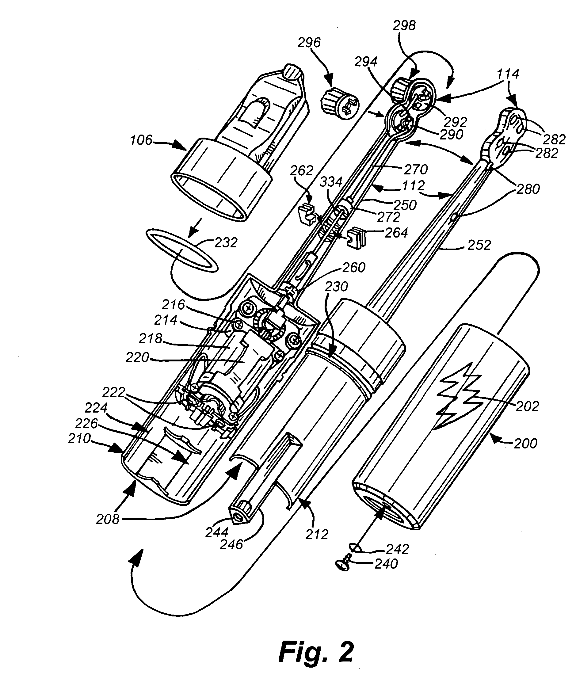
[0005] This invention overcomes the disadvantages of the prior art by providing a power toothbrush with a drive train that is easy to manufacture, reliable in service and that enables multiple heads or other complex design or functional elements. In an illustrative embodiment, the power toothbrush includes a sealed case that encloses a motor with a pinion gear joined to a circular rack that drives an eccentric link that converts unidirectional rack rotation into bi-directional reciprocating linear motion. In one embodiment, the eccentric link is an eccentric pin mounted on the rack that rides in a slot on a drive plate. The plate is joined to a push rod, typically constructed of metal that passes up a hollow toothbrush shaft through an elastomeric seal

Problems solved by technology

Thus, some designs may be easy to manufacture, but unreliable, and vice versa.
The possibility of adding more-complex features, such as multiple moving brush heads is desirable, but may reduce cost ore reliability.

Method used


Image

  • Power toothbrush
  • Power toothbrush
  • Power toothbrush

Examples


Embodiment Construction

[0015] The present application is related to commonly assigned U.S. patent application Ser. No. 10 / 237,902, filed Sep. 9, 2002, by Robert D. Banning entitled TOPPER FOR A POWER TOOTHBRUSH, the teachings of which are expressly incorporated by reference.

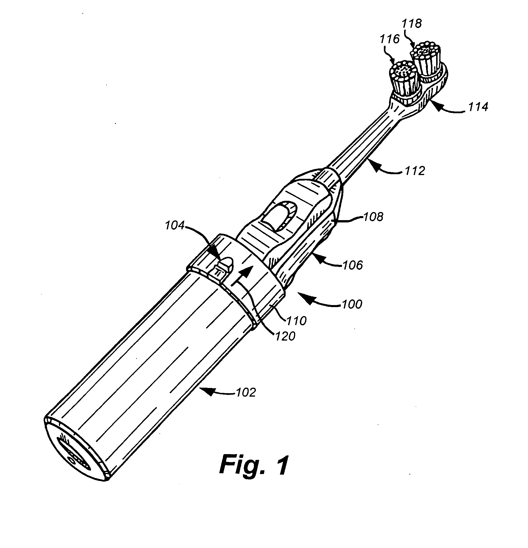
[0016]FIG. 1 shows a power toothbrush 100 according to an illustrative embodiment of this invention. The toothbrush includes a handle region 102, an on / off switch 104, a decorative topper 106 that includes a sculpted feature 108 (in this case a race car) and an apron that is attached to the sculpted feature 110. The topper, and its assembly, is described further with reference to the above-incorporated U.S. patent application Ser. No. 10 / 237,902. The topper 106 is placed over a hollow toothbrush shaft 112 ending in a head assembly 114. The head assembly, in this embodiment, includes two rotationally moving brush heads 116 and 118. The switch 104, when depressed causes the heads to rotate under power of an internal motor to be describe...


PUM


Abstract

A power toothbrush with a drive train that is easy to manufacture, reliable in service and that enables multiple heads or other complex design or functional elements is provided. In an illustrative embodiment, the power toothbrush includes a sealed case that encloses a motor with a pinion gear joined to an eccentric link. This eccentric link can be a circular rack having an eccentric pin that rides in a slot on a drive plate. The drive plate is joined to a push rod, typically constructed of metal that passes up a hollow toothbrush shaft through an elastomeric seal to a head assembly. The head assembly includes one or more moving disks that are each connected to generally circular brush heads, which project outwardly from the head assembly. One disk receives a bent end of the drive shaft in a hole located eccentrically to the axis of rotation. When the circular rack rotates in a single direction, it drives the shaft in a reciprocating motion that, thereby, rotates the disk in a corresponding reciprocating circular motion about its axis. Additional disks can be linked by a short connecting shaft or link to the first disk via eccentric holes—other linkages, such as mating gears between disks can be used to simultaneously drive further disks, thereby providing a multiple moving-head power toothbrush.

Description

[0001] This application is a continuation of U.S. application Ser. No. 10 / 331,799, filed Dec. 30, 2002, which is incorporated herein by reference.FIELD OF THE INVENTION [0002] This invention relates to toothbrushes and more particularly to inexpensive battery-powered power toothbrushes. BACKGROUND OF THE INVENTION [0003] Powered toothbrushes are becoming an increasingly desirable item for both adults and children. A variety of inexpensive semi-disposable and fully disposable powered toothbrushes are now available on the market. In order to interest children in developing good oral hygiene habits, many toothbrushes, including powered toothbrushes, are provided with decoration relevant to childrens' tastes. One of the more elaborate and desired forms of decoration is a sculpted feature applied to a portion of the brush handle. Such sculpted features can represent well-known cartoon characters or any other relevant three-dimensional subject matter including desirable toys. [0004] Some ...

Claims


Application Information

Patent Timeline
IPC IPC(8): A61C17/34
CPCA61C17/3436A61C2203/00A61C17/349
Inventor BANNING, ROBERT D.
Owner THE GILLETTE CO
Learn More