
Method and apparatus for dispensing a predetermined fixed amount of pre-stretched film relative to load girth

a predetermined and fixed amount technology, applied in the direction of packaging goods, transportation and packaging, bundling articles, etc., can solve the problems of excessive film breakage of ring style wrappers, limited amount of containment force applied to loads, supply of excess packaging materials,

Active Publication Date: 2006-11-09
LANTECH COM
View PDF81 Cites 72 Cited by
  • Summary
  • Abstract
  • Description
  • Claims
  • Application Information

AI Technical Summary

Benefits of technology

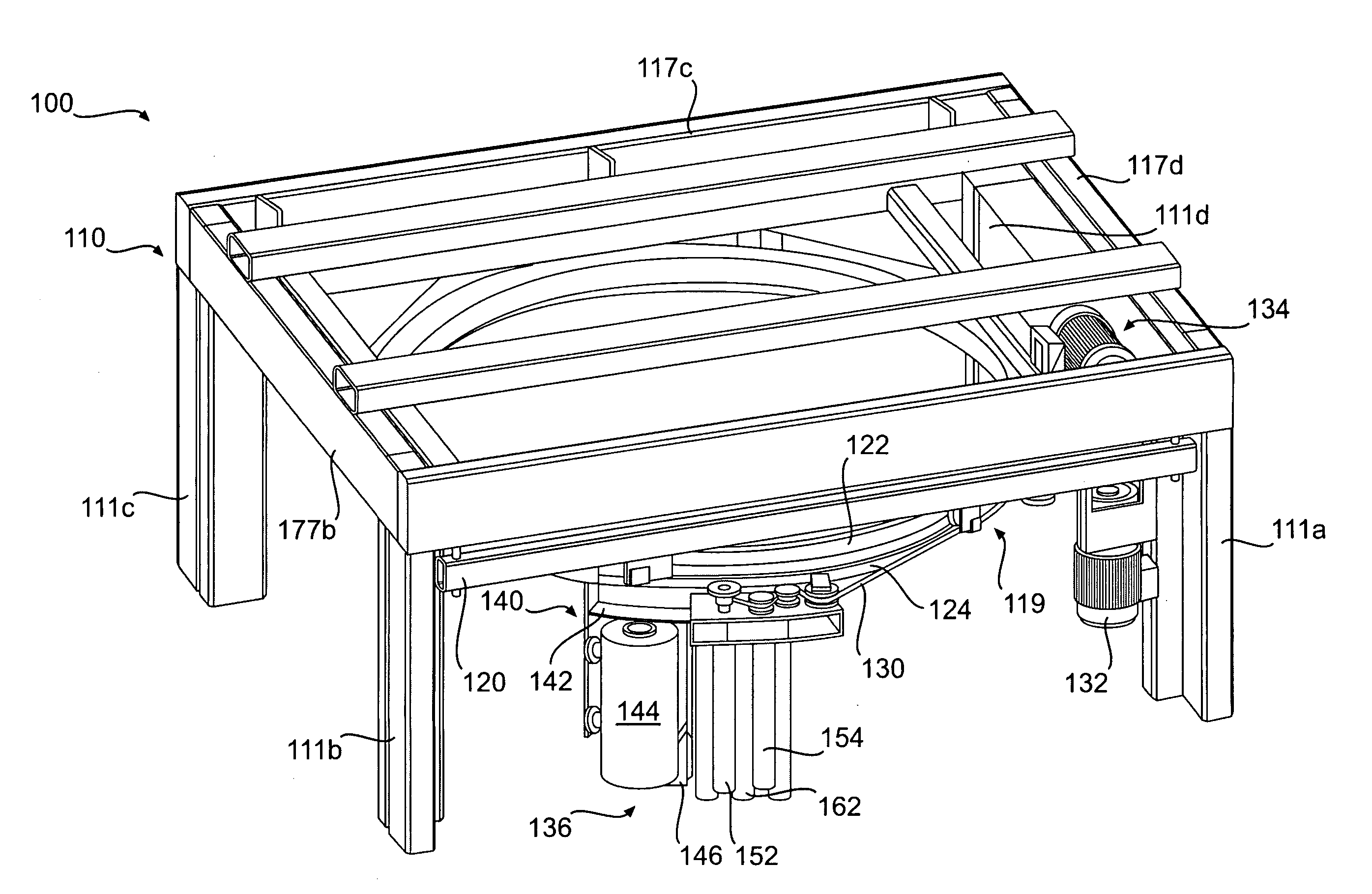
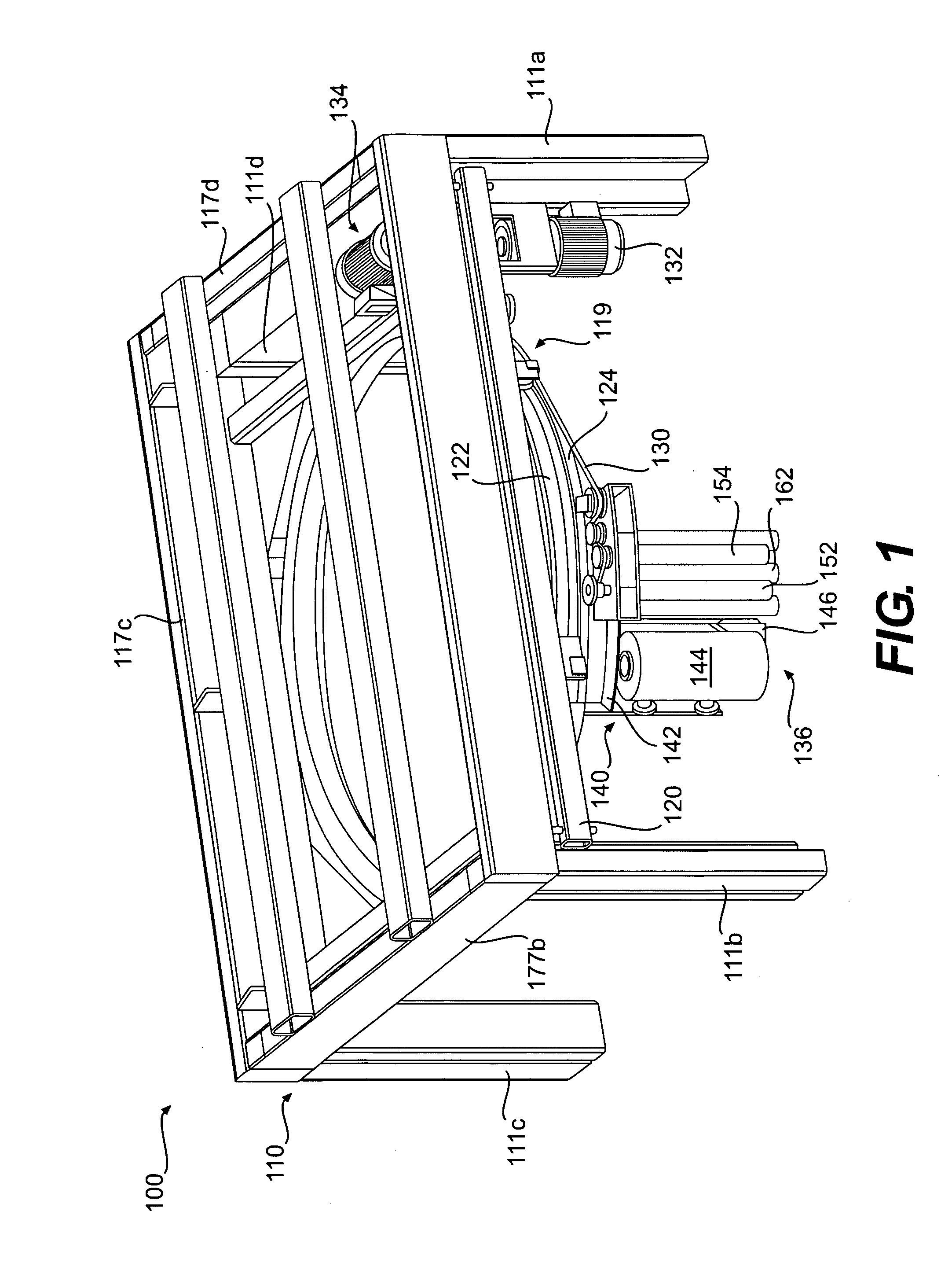
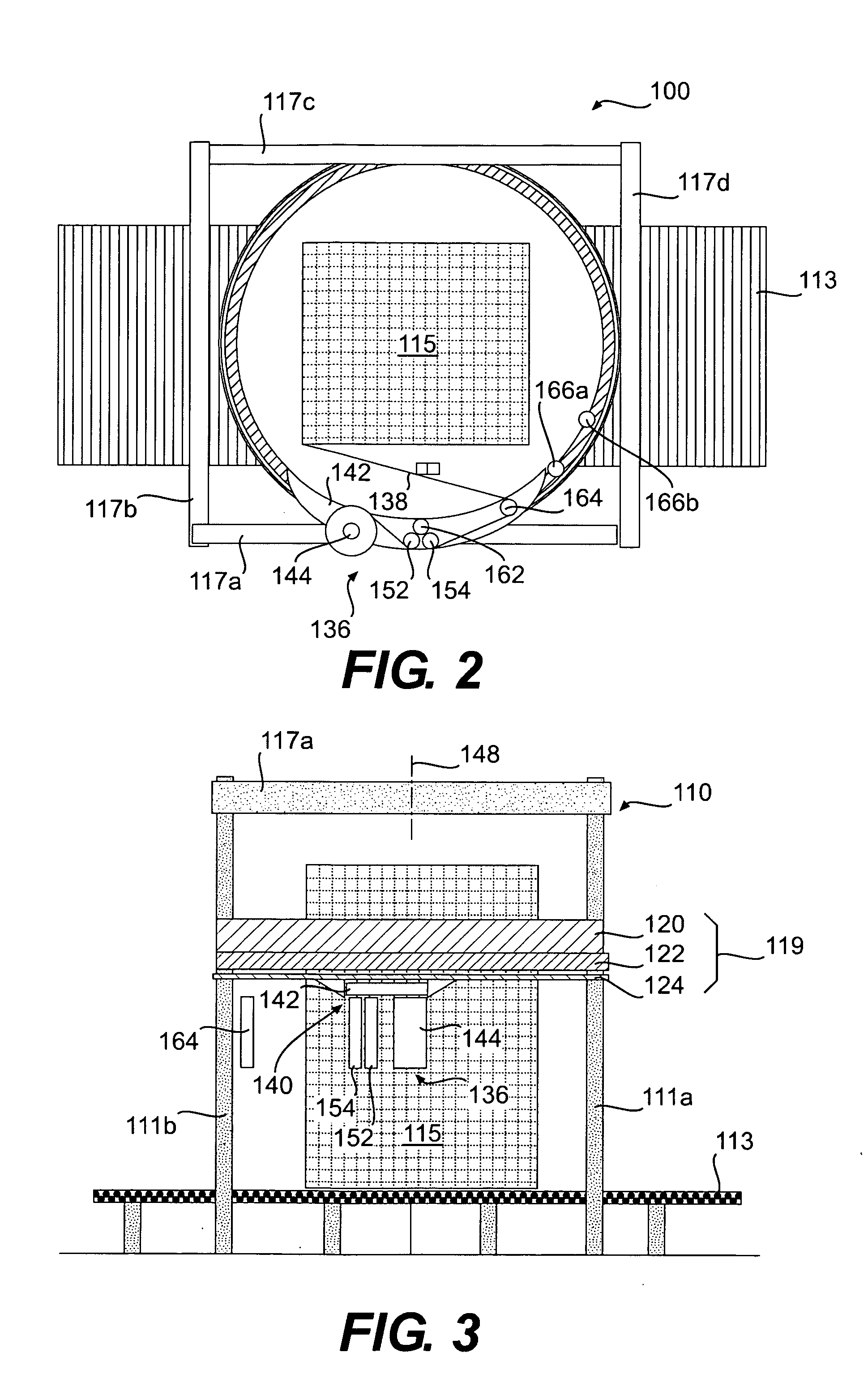
[0018] In another aspect, the presently disclosed embodiments may be directed to an apparatus for stretch wrapping a load. The apparatus may include a rotatable ring. The apparatus may also include a film dispenser having a pre-stretch portion, the film dispenser being mounted on the rotatable ring. The apparatus may further include a drive belt configured to rotate the rotatable ring, wherein the drive belt is carried on a non-rotatable ring and passes over a pulley connected to the rotatable ring. The drive belt may drive the pre-stretch portion of the film dispenser to cause a pre-determined fixed length of film to be dispensed for each revolution of the rotatable ring.

Problems solved by technology

Historically, ring style wrappers have suffered from excessive film breaks and limitations on the amount of containment force applied to the load (as determined in part by the amount of pre-stretch used) due to erratic speed changes required to wrap “non-square” loads, such as narrow, tall loads, short, wide loads, and short, narrow loads.
The non-square shape of such loads often results in the supply of excess packaging material during the wrapping cycle, during time periods in which the demand rate for packaging material by the load is exceeded by the supply rate of the packaging material by the dispenser.
This leads to loosely wrapped loads.
In addition, when the demand rate for packaging material by the load is greater than the supply rate of the packaging material by the dispenser, breakage of the packaging material may occur.
However, when variations in the demand rate are large, fluctuations between the feed and demand rates result in loose packaging of the load or breakage of the packaging material during wrapping.
This embodiment experienced no commercial success due the difficulty of practically achieving that process with market acceptable cost and satisfactory wrap performance.
Accurately setting and maintaining the reference speeds with the disclosed embodiments proved problematic.
With the ever faster wrapping rates demanded by the industry, rotation speeds have increased significantly to a point where the concept of sensing demand change and altering supply speed is no longer effective.
Thus, acceleration cannot be maintained by the feedback mechanisms described above.
Film dispensers mounted on horizontally rotating rings present additional special issues concerning effectively wrapping at high speeds.
All of these devices suffer complexity, cost and maintenance issues.
But even more importantly they add significant weight to the rotating ring which impacts its ability to accelerate and decelerate rapidly.
Film dispensers mounted on vertically rotating rings have the additional problem of gravity forces added to centrifugal forces of high-speed rotation.
High-speed wrappers have therefore required expensive and very heavy two part bearings to support the film dispensers.
Due to the problems described above, use of high speed wrapping has been limited to relatively lower wrap forces and pre-stretch levels where the loss of control at high speeds does not produce undesirable film breaks.

Method used


Image

  • Method and apparatus for dispensing a predetermined fixed amount of pre-stretched film relative to load girth
  • Method and apparatus for dispensing a predetermined fixed amount of pre-stretched film relative to load girth
  • Method and apparatus for dispensing a predetermined fixed amount of pre-stretched film relative to load girth

Examples


Embodiment Construction

[0033] Reference will now be made in detail to the present embodiment of the invention, an example of which is illustrated in the accompanying drawings. Wherever possible, the same reference numbers will be used throughout the drawings to refer to the same or like parts.

[0034] The present invention is related to a method and apparatus for dispensing a predetermined fixed amount of pre-stretched film per revolution of a dispenser around a load during a wrapping cycle. The apparatus includes a rotating ring, a film dispenser including a pre-stretch portion, the film dispenser being mounted on the rotating ring, and a drive system for rotating the ring and driving the pre-stretch rollers of the film dispenser.

[0035] The fixed amount of pre-stretched film dispensed per revolution of the dispenser is predetermined based upon the girth of the load to be wrapped. The girth (G) of a load is defined as the length (L) of the load plus the width (W) of the load times two (2) or G=[2×(L+W)]. ...


PUM

PropertyMeasurementUnit
widthaaaaaaaaaa
widthaaaaaaaaaa
lengthaaaaaaaaaa

Abstract

The present invention provides a method and apparatus for dispensing a predetermined fixed amount of pre-stretched film based upon load girth. A non-rotating ring carries a belt driven by a motor. A film dispenser is mounted on a rotating ring, and the rotating ring includes a pulley that connects to the belt, such that the rotating ring is driven by the belt. Based upon the girth of the load to be wrapped, an amount of pre-stretched film to be dispensed for each revolution made by the rotating ring is determined. Good wrapping performance in terms of load containment (wrap force) and optimum film use is obtained by dispensing a length of pre-stretched film that is between approximately 100% and approximately 130% of load girth. Once the amount of film to be dispensed per revolution is determined, a mechanical ratio of ring drive to final pre-stretch surface speed (i.e., number of pre-stretch roller revolution / ring rotation) can be set. Thus, for each revolution of the rotating ring and dispenser, a predetermined fixed amount of film is dispensed and wrapped around the load.

Description

[0001] This application claims priority under 35 U.S.C. § 119 based on U.S. Provisional Application No. 60 / 669,344, filed Apr. 8, 2005, the complete disclosure of which is incorporated herein by reference.FIELD OF THE INVENTION [0002] The present invention relates to methods and apparatus for wrapping a load with packaging material, and more particularly, stretch wrapping. BACKGROUND OF THE INVENTION [0003] Various packaging techniques have been used to build a load of unit products and subsequently wrap them for transportation, storage, containment and stabilization, protection and waterproofing. One system uses stretch wrapping machines to stretch, dispense and wrap stretch packaging material around a load. Stretch wrapping can be performed as an inline, automated packaging technique that dispenses and wraps packaging material in a stretch condition around a load on a pallet to cover and contain the load. Pallet stretch wrapping, whether accomplished by a turntable, rotating arm, ...

Claims


Application Information

Patent Timeline
Patent Type & Authority Applications(United States)
IPC IPC(8): B65B13/02
CPCB65B11/025B65B2210/18B65B2210/16B65B2011/002
Inventor LANCASTER, PATRICK R. III
Owner LANTECH COM
Learn More