
Liquid crystal display panel and fabricating method thereof

a technology of liquid crystal display panel and fabricating method, which is applied in the field of display devices, can solve the problems of inability to alleviate waviness in the upper array substrate, imperfections in images, and damage to the internal structure of the liquid crystal display panel, so as to prevent waviness of the upper array substrate and improve the uniformity of the cell gap

Active Publication Date: 2006-11-02
LG DISPLAY CO LTD
View PDF5 Cites 12 Cited by
  • Summary
  • Abstract
  • Description
  • Claims
  • Application Information

AI Technical Summary

Benefits of technology

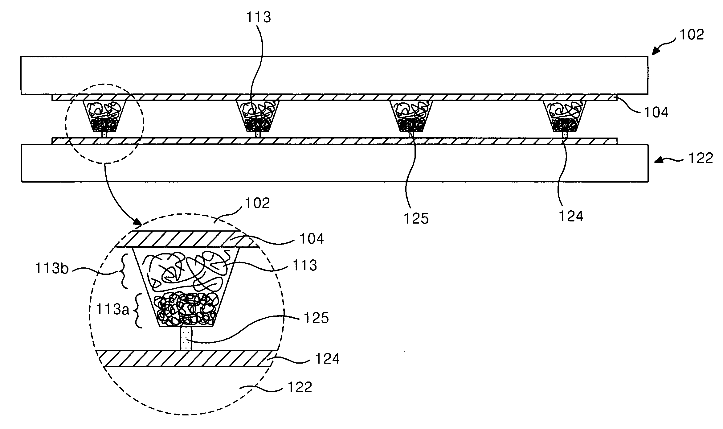
The present invention is directed to a liquid crystal display panel and a fabricating method thereof that addresses limitations and disadvantages of the related art. The invention aims to prevent waviness of the upper array substrate and improve uniformity of the cell gap of the liquid crystal display panel. The invention provides a liquid crystal display panel with an upper array substrate and a lower array substrate positioned opposite each other, a liquid crystal positioned between the substrates, and a spacer positioned between the substrates. The spacer has a first portion with a first hardness and a second portion with a second hardness different from the first hardness. The invention also provides a fabricating method of the liquid crystal display panel by forming a protrusion on the lower array substrate, adding a spacer with two different hardness portions, and bonding the substrates such that the first portion of the spacer contacts the protrusion and the second portion of the spacer contacts the upper array substrate. The technical effects of the invention include improved display quality and stability.

Problems solved by technology

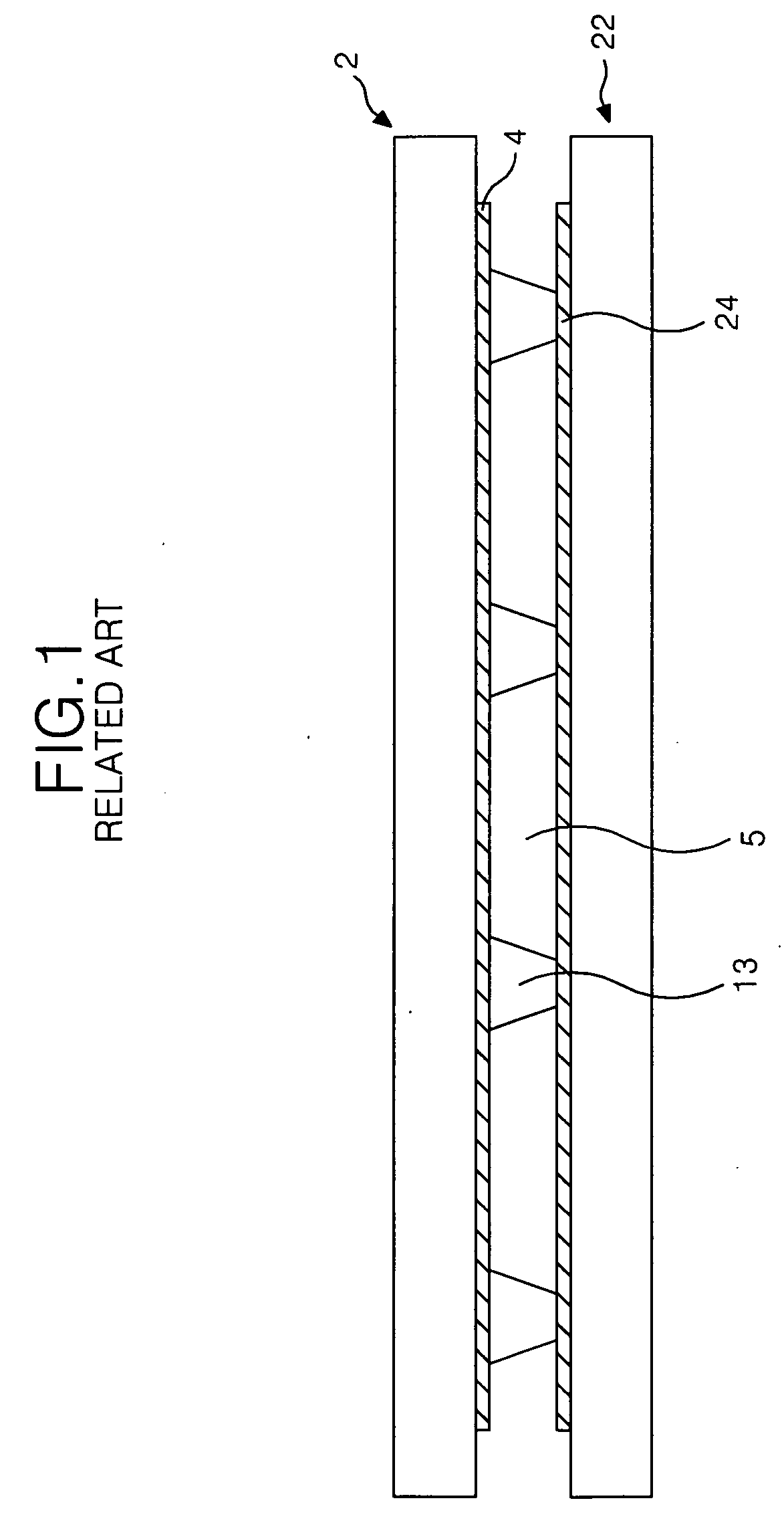
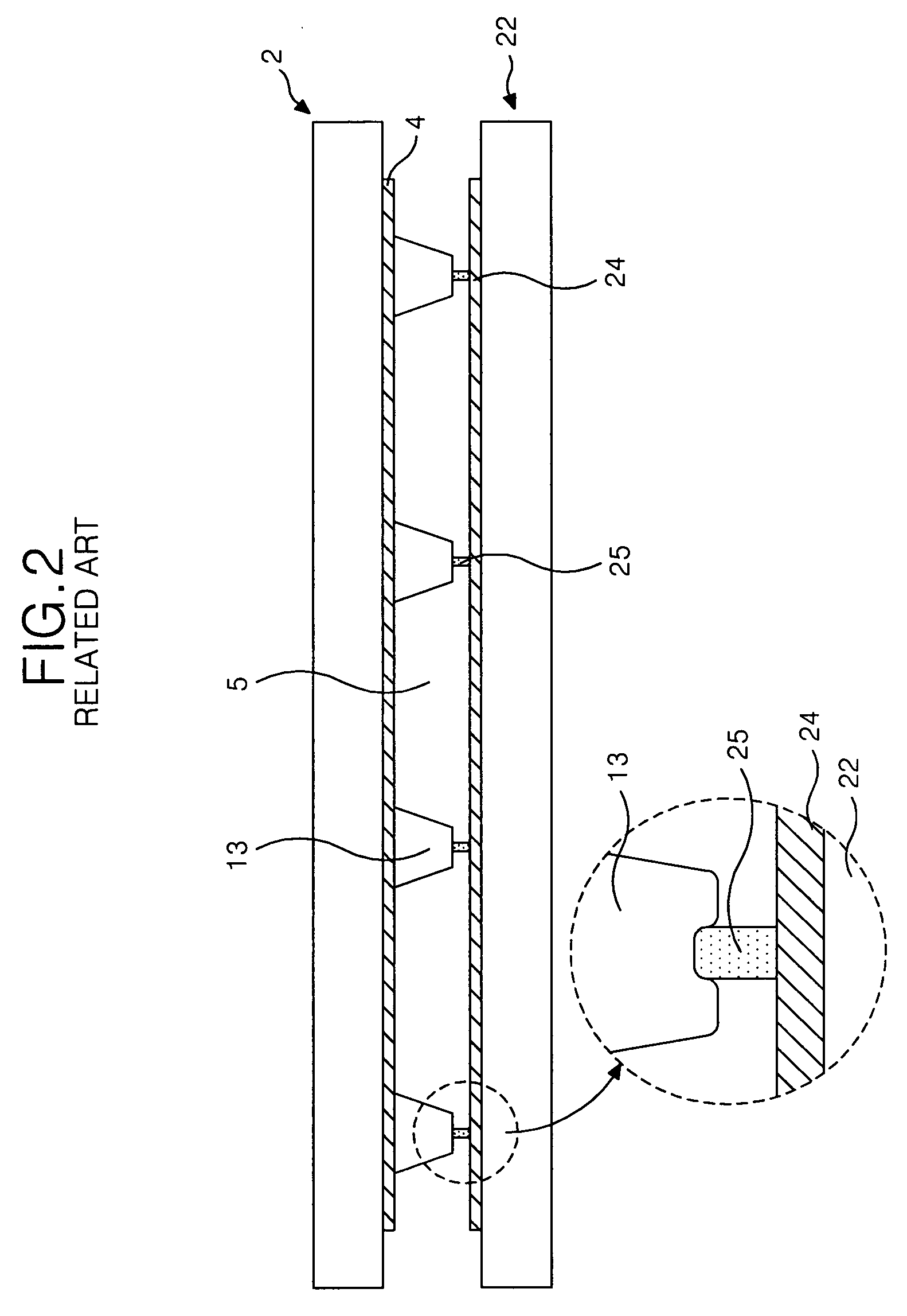
This friction can generate a problem in that internal structures of the liquid crystal display panel can be damaged, such as the signal lines. FIG. 2 is a cross-sectional diagram of a related art liquid crystal display panel having a spacer in contact with a protrusion 25 on the lower array substrate.
However, this pressure can cause the problem of not being able to alleviate waviness in the upper array substrate 2 because of the large static friction between the spacer and the protrusion.
The non-uniformity of the cell gap causes imperfections in the images on the liquid crystal display panel.

Method used


Image

  • Liquid crystal display panel and fabricating method thereof
  • Liquid crystal display panel and fabricating method thereof
  • Liquid crystal display panel and fabricating method thereof

Examples


Embodiment Construction

[0034] Reference will now be made in detail to the preferred embodiments of the present invention, examples of which are illustrated in the accompanying drawings. Hereinafter, with reference to FIGS. 5 to 11, the preferred embodiments of the present invention will be explained.

[0035]FIG. 5 is an experimental data representing that uniformity of the cell gap is improved as a contact density between protrusions and spacers is increased. The uniformity of the cell gap is known to be increased in the case of forming the protrusion and the spacer so that the contact density of the spacer and the protrusion becomes about 50˜100 ppm, while the pressure concentration on the spacers is decreased since the contact area where the protrusions and the spacers are in contact with each other is increased, as shown the experimental result illustrated in FIG. 5. If the contact density of the spacer and the protrusion is increased, there is a problem of deteriorating picture quality such as creating...


PUM

PropertyMeasurementUnit
sizeaaaaaaaaaa
hardnessaaaaaaaaaa
molecular chain structureaaaaaaaaaa

Abstract

A liquid crystal display panel includes an upper array substrate and a lower array substrate that are positioned to be opposite to each other, a liquid crystal positioned between the upper and lower array substrates, a protrusion projecting from the lower array substrate and a spacer positioned between the upper array substrate and the lower array substrate, the spacer having a first portion contacting the protrusion and a second portion contacting the upper array substrate, and the first portion has a first hardness different from a second hardness of a second portion.

Description

[0001] This application claims the benefit of the Korean Patent Application No. P2005-36404 filed on Apr. 29, 2005, which is hereby incorporated by reference in its entirety. BACKGROUND OF THE INVENTION [0002] 1. Field of the Invention [0003] The present invention relates to a display device, and more particularly to a liquid crystal display panel and a fabricating method thereof. Although the present invention is suitable for a wide scope of applications, it is particularly suitable for preventing waviness in the liquid crystal display panel and maintaining a cell gap of the liquid crystal display panel. [0004] 2. Description of the Related Art [0005] Generally, a liquid crystal display device LCD controls the light transmittance of liquid crystal cells in accordance with a video signal, thereby displaying a picture on liquid crystal display panel that corresponds to the video signal. More particularly, the liquid crystal display device includes a liquid crystal display panel in wh...

Claims


Application Information

Patent Timeline
Patent Type & Authority Applications(United States)
IPC IPC(8): G02F1/1339
CPCG02F1/13394G02F1/1339
Inventor YOON, SUNG HOE
Owner LG DISPLAY CO LTD
Learn More