
Moving object detection apparatus, method and program

a detection apparatus and moving object technology, applied in the field of moving object detection apparatus and method, can solve the problems of low reliability of the motion vector, the sn ratio of images corresponding to image signals input from surveillance cameras is not good, and the moving object detection device b>1/b> may fail to track and detect the person hu, etc., to achieve accurate detection of moving objects

Inactive Publication Date: 2006-11-02
SONY CORP
View PDF2 Cites 52 Cited by
  • Summary
  • Abstract
  • Description
  • Claims
  • Application Information

AI Technical Summary

Benefits of technology

[0049] The present invention has been made in view of the above points and is intended to provide a moving object detection apparatus, method and program which can accurately detect moving objects.
[0051] In this manner, the apparatus removes motion vectors arising from moving backgrounds without removing motion vectors arising from moving objects. That previously and effectively prevents the apparatus from confusing motion vectors arising from moving backgrounds with motion vectors arising from moving objects. Thus, the moving object detection apparatus can accurately detect moving objects.
[0053] In this manner, the apparatus according to this method removes motion vectors arising from moving backgrounds without removing motion vectors arising from moving objects. That previously and effectively prevents the apparatus from confusing motion vectors arising from moving backgrounds with motion vectors arising from moving objects. Thus, the moving object detection method can accurately detect moving objects.
[0055] In this manner, the apparatus removes motion vectors arising from moving backgrounds without removing motion vectors arising from moving objects. That previously and effectively prevents the apparatus from confusing motion vectors arising from moving backgrounds with motion vectors arising from moving objects. Thus, this program accurately detects moving objects.

Problems solved by technology

In the case in which the minimum value on the correlation value map shows a distinct negative peak, the motion vector is deemed to have high reliability; and otherwise, the motion vector is deemed to have low reliability.
Therefore, the moving object detection device 1 may fail to track and detect the person HU.
In general, a video surveillance system equipped with those kinds of moving object detection device 1, 20 are often installed in the environment where illumination is not sufficiently bright, and therefore the SN ratio of the images corresponding to the image signals input from surveillance cameras are not good.
The random noise is generated all over the screen, and varies with time.
That causes problems similar to those arising from the overlapping of the background change and the moving object as described above.
Even if the moving object detection device 20 moves the correlation calculation blocks BR2 in conjunction with the tracking, that increases the complexity of the image processing procedure and device configuration, because it has to temporally change the positions of the correlation calculation blocks BR2 in each area independently.
Thus, the above-noted moving object detection device 1, 20 have various kinds of problems such as they have difficulty in accurately tracking and detecting moving objects, because they first set the area (the detection block BR1 or the changing area AR) to the target prior to evaluating the uniformity of “movements” and move the correlation calculation blocks BR2.

Method used


Image

  • Moving object detection apparatus, method and program
  • Moving object detection apparatus, method and program
  • Moving object detection apparatus, method and program

Examples


first embodiment

(1) First Embodiment

(1-1) Configuration of Moving Object Detection Device According to First Embodiment

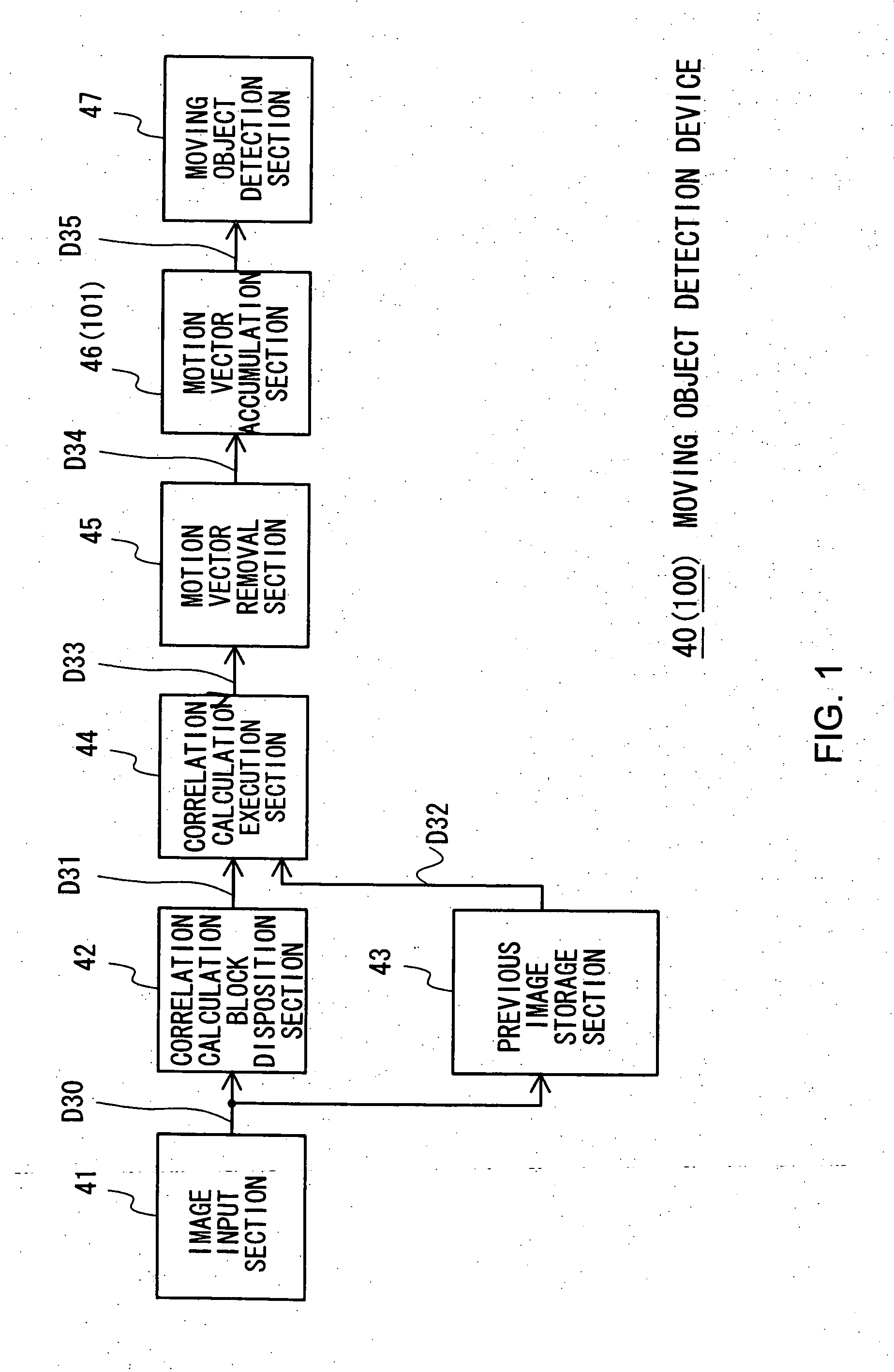
[0106] In FIG. 1, the reference numeral 40 denotes a moving object detection device according to a first embodiment. The moving object detection device 40 for example is installed in surveillance systems such as video surveillance system. The moving object detection device 40 inputs image data D30 (image information) supplied from surveillance cameras (not shown) via an image input section 41 to a correlation calculation block disposition section 42 and a previous image storage section 43.

[0107] As shown in FIG. 2, the correlation calculation block disposition section 42 disposes correlation calculation blocks BR10 (these blocks are indicated by ruled lines in FIG. 2) on the image PT corresponding to the supplied image data D30 in one of the following manners: the correlation calculation block disposition section 42 disposes the correlation calculation blocks BR10 all over the i...

second embodiment

(2) Second Embodiment

(2-1) Configuration of Moving Object Detection Device According to Second Embodiment

[0179]FIG. 26 (the parts of FIG. 26 are designated by the same symbols and marks as the corresponding parts of FIG. 1) shows a moving object detection device 70 according to a second embodiment. The configuration of the moving object detection device 70 is almost similar to that of the moving object detection device 40 (FIG. 1) according to the first embodiment, except that: the correlation calculation block disposition section 42 supplies the correlation calculation block data D31 to the motion vector removal section 71; and the configuration of the motion vector removal section 71 is different.

[0180] As shown in FIG. 27 (the parts of FIG. 27 are designated by the same symbols and marks as the corresponding parts of FIG. 5), the configuration of the motion vector removal section 71 is almost similar to that of the motion vector removal section 45 (FIG. 1) according to the fir...

third embodiment

(3) Third Embodiment

(3-1) Configuration of Moving Object Detection Device According to Third Embodiment

[0201]FIG. 32 (the parts of FIG. 32 are designated by the same symbols and marks as the corresponding parts of FIG. 26) shows a moving object detection device 90 according to a third embodiment. The configuration of the moving object detection device 90 is almost similar to that of the moving object detection device 70 (FIG. 26) according to the second embodiment, except that the device 90 includes a second correlation calculation section 91 and a motion vector integration section 92.

[0202] In the moving object detection device 90 according to the third embodiment, the image data D30 supplied from the image input section 41 is referred to as a first layer image data D30. The above-noted correlation calculation block disposition section 42, which processes the first layer image data D30, is referred to as a first correlation calculation block disposition section 42. In addition, ...


PUM


Abstract

A moving object detection device accurately detects moving objects. The device includes a motion vector calculation section calculating motion vectors from an input image; a motion vector removal section removing a motion vector having high randomness from the calculated motion vectors; a motion vector accumulation section temporally accumulating each motion vector not removed by the motion vector removal section, and calculating an accumulated number of occurrences and an accumulated value of each motion vector; and a moving object detection section determining, based on the calculated accumulated value and calculated accumulated number of occurrences of each motion vector, whether each motion vector corresponds to a moving object.

Description

CROSS-REFERENCE TO RELATED APPLICATIONS [0001] The present application claims priority from Japanese Patent Application No. 2005-075482 filed on Mar. 16, 2005, the disclosure of which is hereby incorporated by reference herein. BACKGROUND OF THE INVENTION [0002] The preset invention relates to a moving object detection apparatus and method, and is preferably applied to a moving object detection device in a video surveillance system, for example. [0003] A video surveillance system equipped with a moving object detection device has been installed in buildings, warehouses and the like for crime prevention. This moving object detection device processes image signals supplied from surveillance cameras to detect a moving object in an image corresponding to the image signals. [0004] It is desirable that the moving object detection device can accurately detect moving objects in images even if the device is affected by the following factors: diffused reflection light caused by water waves; n...

Claims


Application Information

Patent Timeline
Patent Type & Authority Applications(United States)
IPC IPC(8): H04N5/14H04N7/18H04N9/47H04N9/64H04N23/40G06T7/20G06V10/762
CPCG06K9/00771G06K9/6218G06T2207/30232G06T2207/10016G06T7/202G06T7/231G06V20/52G06V10/762G06F18/23E05F7/04E06B7/16E06B3/4609
Inventor KISHIDA, TAKESHI
Owner SONY CORP
Learn More