
Driving method of dual-scan mode display and related display thereof

a dual-scan mode display and driving method technology, applied in the direction of electric digital data processing, instruments, computing, etc., can solve the problems of mismatching of different driver ics, large luminance difference between the oled pixels driven by the driver ics, and serious problems such as above-mentioned display, so as to reduce manufacturing costs and improve yield.

Inactive Publication Date: 2006-11-02
CHI MEI EL +1
View PDF11 Cites 4 Cited by
  • Summary
  • Abstract
  • Description
  • Claims
  • Application Information

AI Technical Summary

Benefits of technology

The present invention provides a driving method for a dual-scan mode display that improves the display's effectiveness. The method involves adjusting the output of the first and second drivers based on the brightness values of the first and second pixels, resulting in a more consistent display across the top and bottom areas. This method also allows for more flexibility in the parameters of the driver ICs, leading to better yield and reduced manufacturing costs.

Problems solved by technology

The above-mentioned display suffers a serious problem, however.
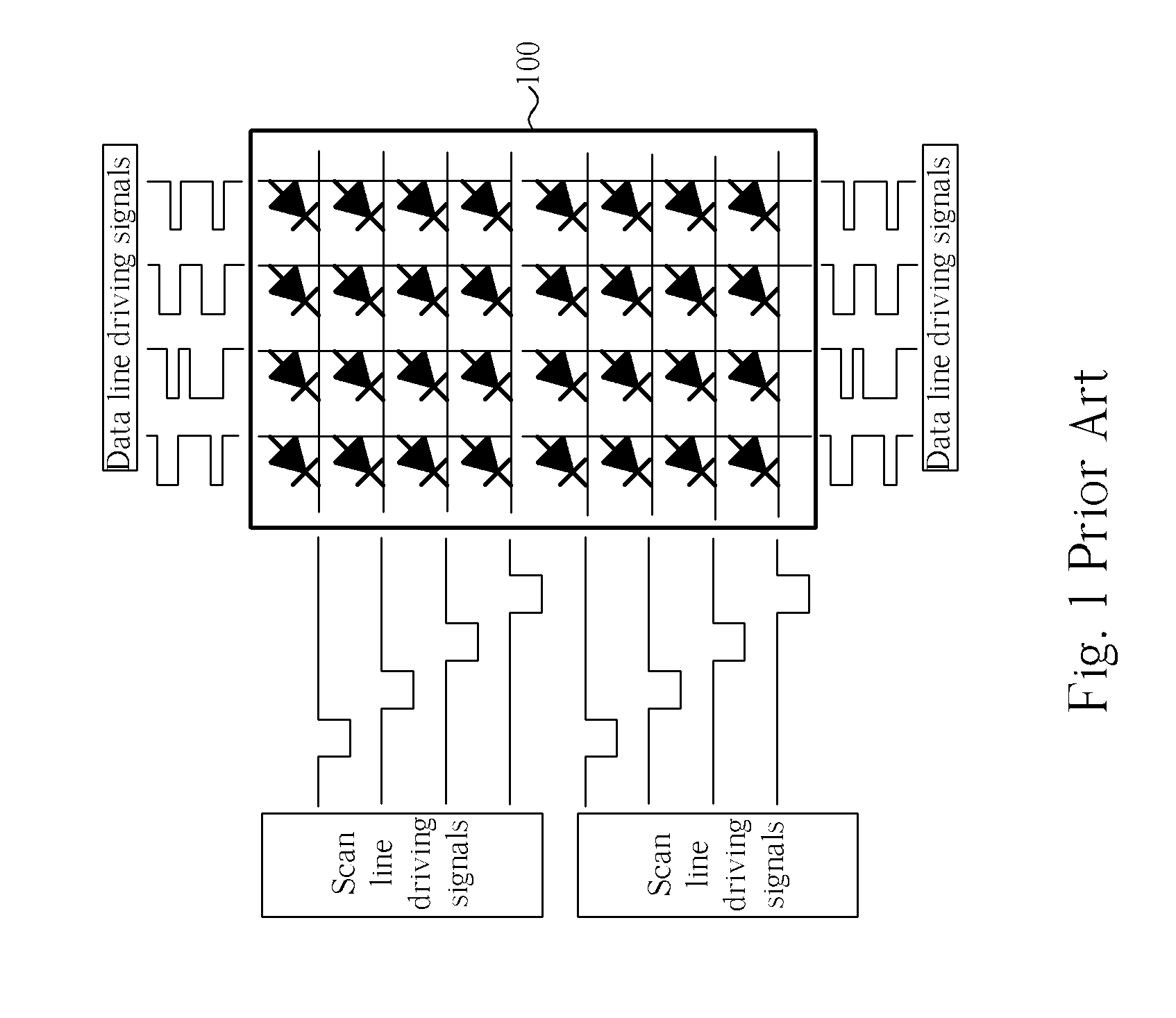
As mentioned previously, two driver ICs are required, but the different driver ICs may be mismatched because the manufacturing processes or operating environments of the driver ICs are different.
Furthermore, if the mismatch between the two driver ICs is more serious, the luminance difference between the OLED pixels driven by the driver ICs is also larger.
For the observer, this makes the display area inconsistent between the top and bottom areas.
Obviously, this solution directly influences the yield of the driver IC.
This means that the limitation of the parameters of the driver IC is more restrictive such that the driver IC becomes more difficult to manufacture.
In short, the above-mentioned solution is not economical.

Method used


Image

  • Driving method of dual-scan mode display and related display thereof
  • Driving method of dual-scan mode display and related display thereof
  • Driving method of dual-scan mode display and related display thereof

Examples


Embodiment Construction

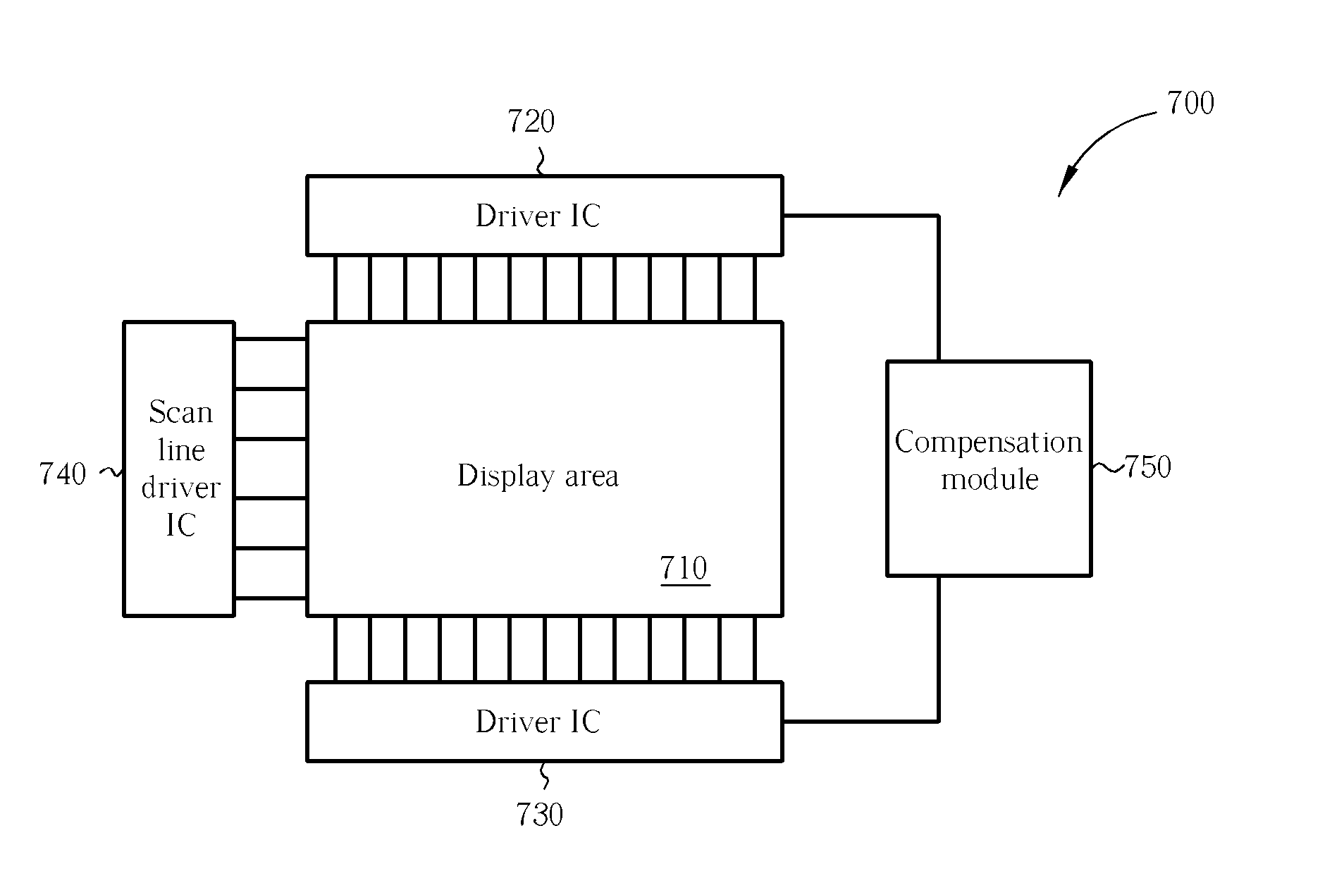
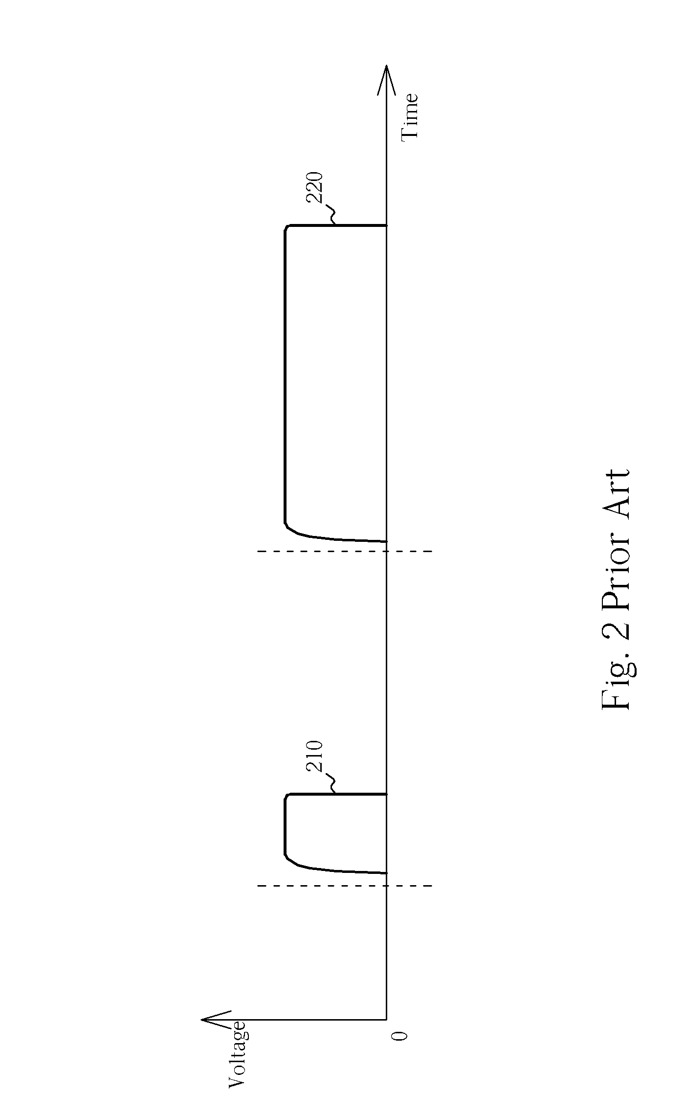
[0025] A novel driving method is disclosed to compensate for the mismatch between the driver ICs. Please refer to FIG. 3, which is a comparative diagram of the present invention PWM signal 300 and the prior art PWM signal 310. As mentioned previously, due to the mismatch between driver ICs, the output powers transferred to the pixels are different. In other words, the output power outputted by one of the driver ICs is smaller than that outputted by the other driver IC. Therefore, as shown in FIG. 3, the present invention PWM signal 300 further comprises a compensation signal ΔV (the bulge area in the pulse width) in each period. This means that the output power transferred to the pixel can be increased such that the luminance of the pixel can also be increased. The present invention can utilize the PWM signal 300 to compensate the driver IC having a smaller output power such that the power outputting difference between the two driver ICs can be eliminated. In this way, the mismatch ...


PUM


Abstract

A method for driving a dual-scan mode display is disclosed. The dual-scan mode display includes a first driver IC and a second driver IC, and the method includes: utilizing the first driver IC to output a first signal according to a gray value to drive a first pixel to generate a first luminance value; utilizing the second driver IC to output a second signal according to the gray value to drive a second pixel to generate a second luminance value; and adjusting the first signal according to the first luminance value and the second luminance value to drive the first pixel to generate a third luminance value; wherein a difference between the third luminance value and the second luminance value is less than a threshold value.

Description

BACKGROUND OF THE INVENTION [0001] 1. Field of the Invention [0002] The present invention relates to a driving method of a display and a related display, and more particularly, to a driving method capable of improving the display effect of a dual-scan mode display and related dual-scan mode display. [0003] 2. Description of the Prior Art [0004] Organic light emission diodes (OLED) are new devices utilized for displays. The OLED has the characteristic of self-light-emitting. Therefore, in contrast to other displays (such as CRTs or LCDs), an OLED display can reduce the required number of parts, therefore making the cost of OLED display lower than conventional displays. [0005] Modern displays need to show more and more information, meaning the display performance of a modern display is also required to be high. If the resolution of the display is high, however, this also means that the number of scan lines of the display should be increased. Considering a constant frame rate of 60 Hz,...

Claims


Application Information

Patent Timeline
Patent Type & Authority Applications(United States)
IPC IPC(8): G09G5/00
CPCG09G3/3216G09G2320/0233G09G2310/0221G09G2310/0205
Inventor WANG, CHUN-FU
Owner CHI MEI EL
Learn More